







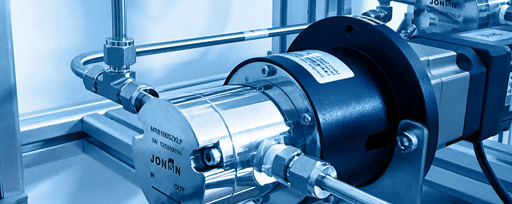
Technical White Paper on Micro Magnetic Gear Pump Industry
Preface
In precision manufacturing and high-end equipment, fluid-handling systems are among the critical links that decide the upper limit of equipment performance. As semiconductor manufacturing, new energy, bio-pharmaceuticals, analytical instrumentation, and data-centre liquid cooling evolve toward higher precision, smaller volume and stronger reliability, traditional pump products increasingly expose structural shortcomings in micro-metering, leak-free sealing, coMPact installation, and medium coMPatibility.
Micro magnetic gear pumps — combining positive-displacement gear-metering with magnetic-coupling leak-free sealing — are achieving high-precision, leak-free, continuously controllable fluid delivery in a micro-scale envelope. They are emerging as an important technical route for precision fluid control. The micro magnetic gear pump is not a simple shrink of any existing pump class; it is a system-level redesign across materials science, precision machining, magnetic-circuit design, and bearing technology.
This white paper targets equipment integrators, R&D engineers, procurement and technical-selection personnel. From the perspective of industry requirements it systematically explains the technical principles, performance boundaries, reliability validation methods, typical application scenarios, engineering selection guide, and industry-trend judgement of micro magnetic gear pumps. We aim to deliver a technical document with engineering reference value, not a product brochure — therefore the paper discusses not only strengths and solutions but also technical limits and unsuitable duty scenarios, helping readers establish a complete technical-cognition framework.
1 Industry Background & Market Pain Points
The market demand for micro magnetic gear pumps is not generated in a vacuum; it is driven jointly by the precision, miniaturisation and greening trends of downstream industries. Understanding these trends is the starting point for understanding the product value.
1.1 The Mega-Trend of Precision Fluid Delivery
In recent years, multiple high-tech industries are undergoing a systemic upgrade of fluid-control requirements. The core features can be summarised as the "Five Highs + One Small":
High precision — semiconductor photoresist coating, developer supply, CMP slurry delivery require flow accuracy of ±1 % or better, while strictly limiting metal-ion leaching.
High micro-volume — analytical instruments (HPLC, ICP-MS) reagent delivery, medical dialysate proportioning, new-energy electrolyte additive injection require flow rates as low as μL/min with long-term stability and zero drift.
High pressure — liquid-cooling circulation, chemical micro-reactor feeding, hydraulic lubrication injection require outlet pressure from several bar to tens of bar; the micro pump must withstand high pressure difference in a limited volume.
High corrosion / high hazard — photoresist, developer, strong acid / alkali solvents, electrolytes etc. are highly corrosive or toxic; shaft-seal leakage causes not only medium loss but also safety hazards and environmental pollution.
High reliability — semiconductor fabs, data centres and medical equipment require 7×24-hour continuous operation; life requirements range from thousands to tens of thousands of hours, and maintenance windows are limited.
Small volume — under the equipment-integration trend, pump installation space is severely constrained; traditional standard-size magnetic pumps often cannot fit.
These six trends overlap to form a clear technical-demand space: high-precision, leak-free, long-life micro-fluid metering delivery in a coMPact envelope. The micro magnetic gear pump is a technical route developed precisely to satisfy this demand space.
| Demand Dimension | Downstream Driver | Core Pump Performance Required | Traditional Pump Shortcoming |
|---|---|---|---|
| High precision | Semiconductor (photoresist coating), analytical instruments (chromatography reagent) | Metering accuracy ±1 % or better; low pulsation; speed–flow linearity controllable | Peristaltic ±3 – 5 %; diaphragm high pulsation |
| High micro-volume | Analytical (μL/min), medical reagent dispensing | Minimum stable flow 0.1 mL/min; micro-step motor control | Diaphragm unstable at tiny flow; syringe cannot run continuously |
| High pressure | Liquid cooling, micro-reactor feed, inkjet supply | Outlet P 5 – 15 bar; reliable seal under high Δp | Peristaltic not high-pressure; micro centrifugal very low efficiency |
| High corrosion / hazard | Semiconductor wet chemicals, strong acid / alkali, electrolyte | All-wetted corrosion-resistant materials; zero leakage; Ex-proof adaptation | Ordinary gear-pump shaft-seal leaks; seals age fast |
| High reliability | Semiconductor fab, data centre, medical device | Continuous run > 5 000 – 10 000 h; maintenance-free design | Peristaltic tube replacement; diaphragm fatigue |
| Small volume | Server internal liquid cooling, portable instruments, aerospace | Pump+motor length < 100 mm; lightweight; flange standardisation | Standard magnetic pumps too large to integrate |
Table 1-1 Demand-matrix interpretation: how the "Five Highs + One Small" map to pump performance
1.2 Structural Shortcomings of Traditional Pump Technologies
Before the maturity of micro magnetic gear pumps, common micro / small pump products on the market each have advantages, but all share structural shortcomings under precision duty:
| Pump Type | Operating Principle | Main Strengths | Core Shortcomings (under Precision Duty) |
|---|---|---|---|
| Ordinary mechanical-seal gear pump | Gear-mesh positive displacement, motor drives through shaft seal | Mature, low cost, wide flow range | Dynamic seal leakage; solvent volatilisation; wear-particle contamination; not for toxic / corrosive media |
| Peristaltic pump | Roller squeezes elastic tube; tube recoil produces suction / discharge | Medium only contacts tube; isolation; dry-run capable | High pulsation; low accuracy (±3 – 5 %); frequent tube replacement; flow drift with tube aging; not for high pressure |
| Diaphragm pump | Diaphragm reciprocation changes chamber volume | Leak-free; can transport particle-laden media | Severe pulsation; tiny flow unstable; diaphragm fatigue; pressure fluctuation |
| Micro centrifugal pump | Impeller rotation generates centrifugal force | Large flow, simple structure | Cannot meter precisely; no self-priming; very low efficiency at small flow / high pressure; not for viscous media |
| Standard magnetic pump (large) | Magnetic-coupling drive, no shaft seal | Leak-free, corrosion-resistant, reliable | Too large / heavy for coMPact devices; insufficient precision at low flow; high cost |
Table 1-2 CoMParison of traditional micro / small pumps
However, in non-precision, large-flow or particle-laden duties, traditional pumps still have significant cost-performance advantages. The value of micro magnetic gear pumps lies in the specific precision-micro-leak-free demand space, not as a one-size-fits-all replacement.
1.3 Pain-Point Analysis Specific to Micro Duty
Beyond the common problems of traditional pumps, the micro chemical duty itself brings a series of specific technical challenges that directly determine whether the product can run reliably in real scenarios:
| Pain-Point Dimension | Specific Manifestation | Effect on Equipment |
|---|---|---|
| Micro-flow stability | At μL/min – mL/min flow, gear tooth-space volume is tiny; machining error is amplified in flow accuracy | Metering error → ratio deviation → process inconsistency |
| Sealing under high Δp | When outlet pressure rises, micro-pump structure strength and seal capability are challenged | Leakage or deformation → flow decay → accuracy drop |
| Corrosive-medium coMPatibility | Photoresist, strong acid / alkali, organic solvents are highly selective on materials | Material incoMPatibility → corrosion, swelling, particle release |
| Explosion-proof requirement | Volatile solvent, flammable medium need to meet Ex standards | Conventional motor+dynamic-seal cannot meet IS requirements |
| Heavy-metal contamination | Semiconductor and analytical instruments require zero metal leaching on medium-contact surfaces | Trace wear of metal gear or bearing → contamination |
| Cramped installation | Dense internal piping; very strict size constraint | Standard pumps cannot integrate; need customised mini design |
| Continuous long run | Fab equipment 7×24 h non-stop; pump life must match equipment cycle | Frequent maintenance / replacement raises downtime cost |
| Wide temperature range | Some media temperature from −20 °C to +80 °C or wider | CTE mismatch → clearance change; magnetic decay; bearing-lube failure |
Table 1-3 Pain points specific to micro chemical duty
These pain points are not isolated; they often stack. For example, semiconductor chemical delivery simultaneously involves micro-flow, high corrosion, heavy-metal contamination, and continuous run. This requires the micro magnetic gear pump to be systematically optimised across material, structure, magnetic circuit and bearing — not simply a downsized standard pump.
2 Technical Principles & Structural Anatomy
This chapter starts from the operating principle and disassembles the core technical architecture of the micro magnetic gear pump layer by layer, analysing the key technical challenges that miniaturisation brings and the corresponding engineering solutions.
2.1 Operating Principle of Micro Gear Pumps
The micro gear pump is a positive-displacement rotary pump. Its operating principle is based on the change of tooth-space volume during gear meshing:
Suction stage: on the side where the gears disengage (suction side), the tooth-space volume increases, creating local negative pressure; the medium is drawn into the tooth space under pressure difference.
Transport stage: the medium is sealed between the tooth space and the pump inner wall, and is carried by the gear rotation to the discharge side.
Discharge stage: on the side where the gears re-engage (discharge side), the tooth-space volume decreases and the medium is squeezed out, forming the output flow.
Each gear rotation completes one suction-discharge cycle per tooth space. Because the tooth-space volume is a fixed geometric parameter, under ideal conditions the output flow is proportional to the speed — this naturally gives the gear pump the characteristic of a metering pump: precise flow control is achieved by precise speed control.
Micro gear pumps usually use external-mesh spur or helical gears. Spur gears are simpler to machine but show clear trapped-oil at high speed; helical gears give smoother meshing transition, helping to lower pulsation and noise, but require higher machining accuracy. Some high-end products use modified tooth profiles to optimise meshing characteristics in the micro-scale.
2.2 Magnetic-Drive Principle
Magnetic drive is the core technology that distinguishes micro magnetic gear pumps from ordinary gear pumps. The basic principle is to use magnetic coupling to achieve power transmission, replacing dynamic sealing with static sealing and eliminating leakage paths from the structure:
| Component | Function Description | Technical Key Points |
|---|---|---|
| Outer magnetic ring (drive ring) | Mounted on the motor end, rotates with motor shaft, generates rotating magnetic field | High-performance NdFeB or SmCo permanent magnets to ensure no magnetic decay at high T |
| Containment can (isolation shell) | Fixed between pump body and motor, completely separates medium chamber from outside | Non-magnetic material; wall thickness balances magnetic transmission efficiency and pressure bearing |
| Inner magnetic ring (driven ring) | Mounted on the pump gear shaft, rotates synchronously driven by outer ring | Must resist medium corrosion; high-T duty must consider magnet temperature coefficient |
| Sealing structure | O-ring or gasket between pump body and can for static seal | Few reliable static-seal points; foundation of "zero leakage" |
Table 2-1 Components and function of the magnetic drive
During operation, the motor drives the outer magnetic ring; the alternating N/S poles generate a rotating magnetic field, which penetrates the non-magnetic containment can and drives the inner ring synchronously, which in turn drives the gear shaft. Because the containment can physically isolates the medium chamber from the outside world, there is no rotating shaft penetrating the pump body — this is the essence of the "shaftless" structure.
2.3 Technical Challenges of Miniaturisation
Scaling a magnetic gear pump down to micro size is not a proportional shrink. Several physical quantities do not scale proportionally after the size shrink, bringing a series of unique engineering challenges:
2.3.1 Ultra-small Gear Machining
Micro gear-pump gear modules may be as low as 0.3 – 0.8 mm, with tooth width only a few mm. Such small gears demand extremely high machining accuracy:
tooth-profile error must be controlled at μm level, otherwise tooth-space volume inconsistency directly causes flow pulsation and metering-accuracy drop;
surface roughness affects friction, wear and medium shear — Ra < 0.4 μm is required;
radial clearance (gear to housing) and axial clearance (gear face to side plate) must be precisely controlled in 5 – 15 μm — too large → internal leakage and efficiency drop; too small → seizure risk;
non-metal gears (PEEK, ceramic) require very different processes from metal gears — special moulding or precision grinding is needed.
2.3.2 Magnetic-Circuit Design
After miniaturisation the magnet-ring volume drops markedly, and the available magnetic-coupling force (torque) decreases with it. Achieving sufficient torque transmission within the limited volume is the core challenge of magnetic-circuit design:
pole count, pole-arc coefficient and air-gap thickness must be optimally matched for torque density;
thicker can increases the air gap and reduces torque transmission efficiency, but thinner can compromises pressure bearing — must be precisely balanced;
high-T operation reduces NdFeB magnetic performance (coercivity temperature coefficient ≈ −0.6 %/°C); temperature margin must be reserved at design;
controlled-slip protection: in overload, controlled slip rather than catastrophic failure; detection means must also be set to identify slipping in time.
2.3.3 Containment-Can Selection & Eddy-Current Heating
The containment can is a key component of magnetic transmission. When the outer ring rotates, if the can is conductive, the alternating magnetic field induces eddy current in the can wall and produces Joule heat — "eddy loss". In a micro pump, because the heat-dissipation area is small, eddy heating is more significant:
metal cans (316L, Hastelloy) have relatively large eddy loss; temperature rise may affect medium stability and magnet performance;
non-metal cans (PEEK, CFRP) eliminate eddy loss, but pressure bearing and wall-thickness uniformity control are challenges;
thermo-magnetic coupled analysis should be done at design to evaluate steady-state T rise; add heat-dissipation structures or select low-loss materials when necessary.
2.3.4 Bearing Matching & Lubrication
Micro magnetic gear pumps typically use medium self-lubrication — the pumped medium itself acts as lubricant. Two challenges arise:
low-viscosity media (water, solvent) have weak lubricating-film load capacity; at high speed, boundary or dry friction occurs, accelerating bearing wear;
if micro-particles or crystallisation products exist in the medium, they act as abrasives and accelerate bearing and gear wear.
Common bearing materials include SiC, alumina (Al₂O₃), PEEK / CFRP composites — selection depends on medium properties, speed and load. Some products allow short-time dry running (seconds to tens of seconds) via self-lubricating materials, but prolonged dry running still causes overheat damage.
2.3.5 Thermal-Management Challenge after Miniaturisation
Among the four challenges above (gear machining, magnetic-circuit design, can material, bearing lubrication), there is one cross-cutting hidden factor — heat. After miniaturisation the heat-dissipation area shrinks sharply and multiple internal heat sources stack, making thermal management the key reliability bottleneck. There are three main heat sources in a micro pump:
Friction heat: gear–bearing friction — micro pumps have small clearance and high linear speed, so friction power density exceeds large pumps;
Eddy heat: eddy loss in the metal containment can — alternating field in the conductive can wall, directly converted to Joule heat;
Medium-conducted heat: the pumped medium itself brings heat — when conveying high-T medium, heat is conducted through the pump body into the magnet and bearing areas.
| Affected Component | High-T Effect Mechanism | Stacked Consequence | Countermeasure |
|---|---|---|---|
| Permanent magnet | T rise drops coercivity & remanence (NdFeB ≈ −0.6 %/°C) | Torque ↓ → easier magnetic slip → slip heats more → vicious cycle | SH / UH high-T grades; control medium T; non-metal can to eliminate eddy |
| Bearing | High T → medium viscosity ↓ → lube film thins → boundary friction → wear | Bearing clearance ↑ → gear misalignment → internal leakage ↑ → accuracy ↓ | High-T ceramic bearings (SiC / Al₂O₃); lower speed to lower PV |
| Seal | High T accelerates elastomer ageing (compression set, hardness change, swelling) | Seal resilience ↓ → micro-leak at static point → failure | FFKM perfluoroelastomer (> 300 °C); periodic replacement; control T |
| Medium | T rise in pump chamber changes viscosity & density → flow characteristic drift | Metering-accuracy offset; medium may decompose or polymerise (photoresist) | Thermo-magnetic-fluid coupled simulation; external cooling if needed |
Table 2-2 Stacked effect of three heat sources on key pump components
In actual design thermal management requires systematic thinking: use a non-metal containment can to eliminate the largest heat source (eddy); use high-T magnets to widen temperature margin; optimise bearing PV value to lower friction heat; add fins or forced-air cooling on the housing when necessary. For high-T medium duty, also evaluate the margin between medium temperature and each component's temperature limit to ensure no thermal failure under the worst-case combined duty.
2.4 Breakdown of Core Components
Although small, micro magnetic gear pumps have very high component-level technical content. Each key component is broken down by function below:
| Component | Function | Key Design Parameters | Common Materials |
|---|---|---|---|
| Gear assembly | Positive-displacement metering core, determines flow accuracy & pulsation | Tooth count, module, profile modification, face width, clearance | PEEK, alumina ceramic, 316L, Hastelloy |
| Magnetic-coupling assembly | Contactless power transmission, leak-free drive | Magnet grade, pole count, air gap, torque margin | NdFeB N42SH / N38UH, SmCo |
| Containment can | Physical barrier between medium chamber and outside world | Wall thickness, material magnetism, pressure rating, eddy loss | PEEK, 316L, Hastelloy C276, CFRP |
| Bearing / sleeve | Supports gear shaft, carries radial & axial load | Material hardness, PV value, clearance, self-lubrication | SiC, Al₂O₃, PEEK / CFRP |
| Pump body / cover | Houses gears and medium, bears internal pressure | Flow-channel layout, wall thickness, seal-face accuracy | 316L, Hastelloy, PEEK, PTFE liner |
| Seals | Static seal ensures zero leakage at joints | Medium coMPatibility, compression ratio, T range | FKM, FFKM, EPDM, PTFE |
| Drive motor | Provides rotation power, controls flow output | Torque, speed range, control accuracy, pulse resolution | Stepper, BLDC, servo motor |
Table 2-3 Breakdown of core components
2.5 Material System & Selection Logic
Material selection is the core means to adapt the micro magnetic gear pump to different medium duties. Different materials trade off corrosion resistance, mechanical strength, wear resistance, temperature range, and processability; system-level matching is required for a specific medium:
| Material | Corrosion-Resistance Characteristics | Mechanical / Wear Performance | Typical Applicable Media | T Range |
|---|---|---|---|---|
| PEEK (poly-ether-ether-ketone) | Resists most organic solvents, weak acids / alkalis | High strength, self-lubricating, low density | Photoresist, developer, reagent, ink | −40 to +250 °C |
| Silicon carbide (SiC) | Resists strong acid / alkali, high-concentration solvents | Very high hardness, excellent wear resistance, low friction | Strong-corrosion chemicals, CMP slurry | −50 to +200 °C |
| Alumina (Al₂O₃) | Resists acid / alkali, anti-oxidation | High hardness, insulating, wear-resistant | Analytical reagent, solvent, DI water | −50 to +200 °C |
| 316L stainless | Medium-corrosion, food-grade | High strength, good machinability | Food / beverage, pharma, coolant, mild chemicals | −50 to +200 °C |
| Hastelloy C276 | Strong acid (HCl, H₂SO₄, chloride) | High strength, SCC-resistant | Strong-corrosion chemicals, wet HCl, hypochlorite | −50 to +250 °C |
| PTFE / CFRP composite | Almost universally corrosion-resistant ("plastic king") | Self-lubricating, low friction, low strength | HF, aqua regia, and other extreme corrosive media | −50 to +180 °C |
Table 2-4 Material-coMParison matrix
Material selection must follow the "full medium-contact-chain matching" principle — every part in contact with the medium (gear, bearing, pump inner wall, seal, containment can inner surface etc.) must be coMPatible with the medium. Any incorrect material choice can cause corrosion-product contamination, component failure, or seal leakage.
3 Performance Indicators & Reliability Validation
A technical white paper must be supported by data and test methods, not just concepts. This chapter establishes a data-driven performance-validation system for micro magnetic gear pumps from three layers: core performance dimensions, key test items, and common failure modes.
3.1 Core Performance Dimensions
Evaluating the performance of a micro magnetic gear pump cannot rely only on flow and pressure. A complete performance profile should include the following dimensions:
| Performance Dimension | Definition | Typical Parameter Range (Reference) | Effect on Application |
|---|---|---|---|
| Flow range | Min-to-max flow range over which the pump can stably output | 0.1 mL/min – 2 000 mL/min (large variation across models) | Determines whether the process flow range can be covered |
| Metering accuracy | Deviation between set flow and actual flow | ±1 % to ±3 % (steady state, specific viscosity) | Directly affects ratio accuracy & process consistency |
| Repeatability | Consistency of multiple runs at the same setpoint | ±0.5 % to ±2 % | Affects batch-to-batch repeatability & traceability |
| Outlet pressure | Upper outlet pressure the pump can continuously withstand | 3 bar – 15 bar (high-P models up to 20 bar+) | Determines whether system back-pressure can be overcome |
| Flow pulsation | Amplitude of flow fluctuation within a gear cycle | Pulsation rate 5 % – 15 % (depends on profile & speed) | Affects coating uniformity and analytical baseline stability |
| Viscosity coMPatibility | Stable viscosity range of media that can be conveyed | 0.5 cP – 500 cP (some models up to 2 000 cP) | Determines conveyable media types |
| Speed range | Working speed range the motor can stably drive | 50 – 3 000 rpm (stepper drive) | Affects flow-regulation range & pulsation characteristics |
| Self-priming | Suction capability when the pump starts from rest | 0.5 – 2 m head (medium-related) | Affects system start-up procedure design |
Table 3-1 Core performance dimensions of micro magnetic gear pumps
Note that the parameters above are not independent — metering accuracy drifts with viscosity; pressure rise increases internal leakage and reduces effective flow; too low a speed increases the pulsation share. Therefore performance evaluation must be done under clear medium conditions (viscosity, temperature, density) and system conditions (back pressure, piping resistance).
3.2 Key Test Items
3.2.1 Leak-Free Verification Test
Purpose: verify static-seal integrity of the magnetic-drive structure; ensure no leakage across the full pressure-difference range.
Pressure-hold test: block outlet; pressurise inlet to 1.3 – 1.5× rated; hold 10 – 30 min; observe pressure drop & external leakage.
Helium leak test: helium mass-spectrometer leak detection on critical seal surfaces; leak rate < 1×10⁻⁶ Pa·m³/s (per application).
Cyclic pressure test: 0 – rated cycle more than 1 000 times; verify seal fatigue reliability.
3.2.2 Long-Life Endurance Test
Purpose: evaluate pump life & performance decay under continuous duty.
Run continuously at rated duty (flow, pressure, medium); record flow-decay curve, noise change, current fluctuation.
Typical test duration: 2 000 – 5 000 h (depending on application); some critical applications require 10 000 h+.
After test, dismantle and inspect gear wear, bearing clearance change, magnet demag etc.
3.2.3 Medium-CoMPatibility Test
Purpose: verify chemical stability and long-term coMPatibility of pump materials in the target medium.
Immersion test: immerse material coupons in the target medium for a specified time (72 h / 168 h / 30 d); detect weight change, dimensional change, mechanical-property change.
Circulation test: cycle the target medium under real duty; monitor medium-purity change, particle increase, material leaching.
Key media to test: photoresist (PGMEA etc.), NMP, IPA, electrolyte, strong acid / alkali, DI water.
3.2.4 Environmental-Adaptability Test
| Test Item | Test Condition | Acceptance Criterion |
|---|---|---|
| High-T operation | Medium T +60 °C to +80 °C; continuous run 24 h | Flow-accuracy offset ≤ ±5 %; no leakage; no abnormal noise |
| Low-T operation | Medium T −10 °C to −20 °C; continuous run 24 h | Normal start; flow-accuracy offset ≤ ±5 % |
| Thermal cycling | −20 °C ↔ +60 °C, 10 cycles | No seal failure; performance recovers |
| Vibration test | 5 – 500 Hz, 1 – 2 Grms, each axis 2 h | No structural loosening; no leakage; performance normal |
| Shock test | 15 g, 11 ms, each axis | No structural damage; function normal |
Table 3-2 Environmental-adaptability test matrix
3.2.5 Dry-Running Tolerance Test
Purpose: evaluate short-time dry-running capability. Magnetic gear pumps in principle do not allow dry running, but real use inevitably includes transient dry-run scenarios such as start-up venting and medium switching.
Run at rated speed without medium; record bearing T rise, torque change, abnormal sound.
Typical dry-run tolerance: 10 – 60 s (depending on bearing material & speed); beyond this time must stop immediately.
Self-lubricating bearings (e.g. carbon-fibre PEEK) have better dry-run tolerance than pure ceramic bearings.
3.2.6 Accelerated Life Test (ALT)
For high-reliability industries such as semiconductor and aerospace, conventional rated-duty long-life tests lasting thousands of hours cannot meet product-iteration verification timelines. Accelerated Life Testing (ALT) applies combined stresses above rated conditions to trigger potential failure modes in a much shorter time and extrapolate equivalent life at rated duty.
| Acceleration Dimension | Acceleration Method | Acceleration Factor Estimate | Failure Mode of Concern |
|---|---|---|---|
| Temperature acceleration | Raise medium / ambient T by 10 – 20 °C above rated upper limit | Every +10 °C roughly ×2 reaction rate (Arrhenius) | Seal ageing; magnet demag; material creep |
| Speed acceleration | Continuous run at 1.2 – 1.5× rated speed | Speed × N → cycles × N → fatigue life equivalently shortened | Bearing wear; gear-tooth fatigue |
| Pressure acceleration | Outlet P raised to 1.2 – 1.3× rated | Load ↑ → wear rate roughly linear | Seal failure; increased magnetic slip frequency |
| Combined stress | Temperature + speed + pressure simultaneously (orthogonal design) | Combined factor = product of factors (correct for interaction) | Multi-factor coupling failure; thermo-mech-mag cross-effect |
Table 3-3 ALT acceleration dimensions
Key ALT principle: acceleration stress must not introduce failure mechanisms absent at rated duty ("acceleration validity" check). E.g. temperature acceleration must not exceed the magnet Curie T causing irreversible demag — that failure does not occur at normal duty and would invalidate the life extrapolation. A typical ALT flow: identify critical failure modes → choose acceleration stresses → design the experiment matrix → run & record failure times → fit accelerated-life curve with a statistical model (Weibull etc.) → extrapolate rated-duty life.
3.3 Common Failure-Mode Analysis & Optimisation
Understanding failure modes is the prerequisite for reliable selection and use. The most common failure modes of micro magnetic gear pumps in real applications, with their root causes and optimisation directions:
| Failure Mode | Root Cause | Manifestation | Optimisation Direction |
|---|---|---|---|
| Magnetic slip | Load torque exceeds magnetic coupling force (system back-P surge, medium viscosity rise, foreign-body capture) | Motor running normally but flow drops or stops; abnormal T rise near can | Reasonable torque margin; P protection & overload detection; high-T magnets |
| Bearing wear | Insufficient medium lubrication; particle abrasion; excessive PV value | Flow decays gradually; noise rises; shaft-end play grows | Match bearing material to medium viscosity; inlet filter; control speed |
| Medium crystallisation seizing the pump | Medium crystallises or solidifies in pump chamber (photoresist low-T, salt-solution evaporation crystallisation) | Pump locked, cannot rotate; motor overload alarm | Add flush line; flush pump chamber with coMPatible solvent before stop; insulation design |
| Containment-can eddy heating | Metal can eddy loss under high-frequency alternating field | Can outer T rises; abnormal medium T rise; high T → magnetic decay | Non-metal can (PEEK etc.); optimise pole count to lower frequency; add cooling |
| Seal ageing | Material incoMPatibility; long-term high-T ageing; compression set | Micro-leak at static point; visible seal deformation or swelling | Strict seal material match; periodic replacement; control T |
| Gear wear / pitting | Long-term wear; hard particles in medium; cavitation damage | Flow accuracy drop; internal leakage rise; noise & vibration | High-hardness gear (ceramic); inlet filter; avoid cavitation |
| Magnet demag | Long-term T above magnet Curie; slip-induced local heating | Torque transmission drop; frequent slip; flow unstable | High-coercivity magnets (UH / SH); control T; slip protection |
Table 3-4 Common failure modes & root causes
4 Downstream Industry Application Scenarios
This chapter breaks down the typical application scenarios of micro magnetic gear pumps by industry. For each scenario we start from duty requirements, analyse the pain points of the existing solution, explain the value of the micro magnetic gear-pump solution, and provide typical parameter reference.
4.1 Semiconductor Industry
4.1.1 Duty Requirements
Photoresist coating: flow accuracy ±1 % or better; very low pulsation; no metal-ion contamination (Fe, Na, K below ppb level).
Developer / stripper supply: strongly alkaline or acidic media; needs corrosion resistance and leak-free.
CMP slurry delivery: contains nano-abrasive particles; very high wear-resistance requirement.
Wet-cleaning chemicals: multiple strong-acid blending; frequent medium switching.
4.1.2 Pain Points of Existing Solutions
Traditional mechanical-seal gear pumps have shaft-seal micro-leakage that causes chemical vapours to corrode the equipment environment; metal gear and bearing wear particles may contaminate the wafer. Peristaltic pump pulsation and tube-particle shedding are not suitable for precision coating. Diaphragm pump flow pulsation cannot meet precision-ratio requirements.
4.1.3 Solution
Micro magnetic gear pump adopts PEEK or ceramic gear + non-metal containment can, achieving zero metal leaching across all medium-contact surfaces; static-seal structure ensures zero leakage; positive-displacement metering ensures ±1 % flow accuracy; stepper-motor drive enables pulse-level flow control.
| Parameter | Typical Reference Value |
|---|---|
| Flow range | 0.5 – 50 mL/min |
| Metering accuracy | ±1 % (steady state, medium viscosity 5 – 50 cP) |
| Outlet pressure | 3 – 8 bar |
| Medium-contact materials | PEEK gear + SiC bearing + PEEK can + FFKM seal |
| Metal-leaching control | Fe / Na / K < 1 ppb (all-non-metal flow path) |
Table 4-1 Semiconductor-industry parameter reference
4.1.4 Selection Risk Alerts
Bubble risk: if the medium contains bubbles (e.g. insufficiently degassed photoresist), install an online degasser before the pump inlet, otherwise bubbles cause flow surge and coating defects.
Abrasive wear: CMP slurry contains nano-hard particles; long-term operation accelerates gear / bearing wear. SiC ceramic gear + SiC bearing recommended, with shortened maintenance intervals.
Temperature sensitivity: photoresist is temperature-sensitive (high T may trigger polymerisation). Evaluate pump-chamber T rise effect on the medium; consider non-metal can to eliminate eddy heat.
4.2 Analytical Instruments & Medical Equipment
4.2.1 Duty Requirements
HPLC: mobile phase delivery needs extremely low pulsation, high repeatability; flow from μL/min to mL/min.
Biochemical analyser: reagent micro-dispensing; rapid response, precise metering, no cross-contamination.
Medical dialysis / infusion equipment: extremely high safety requirements; medium is saline, dialysate etc. biocoMPatible liquid.
4.2.2 Pain Points
HPLC traditionally uses piston pumps — accurate yet structurally complex, high maintenance, and pulsation must be suppressed by a damper. Biochemical analysers often use syringe pumps — dispensing speed limited and no continuous supply. Peristaltic pump accuracy & pulsation do not meet analytical-grade requirements.
4.2.3 Solution
The micro magnetic gear pump can serve as a precision metering or transfer pump in analytical instruments, paired with micro-step stepper motors for smooth low-flow output. In medical devices, the leak-free structure meets biosafety requirements; PEEK / ceramic materials meet FDA & USP Class VI biocoMPatibility standards.
| Parameter | Typical Reference Value |
|---|---|
| Flow range | 0.1 – 20 mL/min (analytical grade) / 1 – 100 mL/min (medical grade) |
| Metering accuracy | ±0.5 % (analytical grade, steady state) / ±2 % (medical grade) |
| Flow pulsation | Pulsation rate < 5 % (with damper can drop to < 2 %) |
| Medium-contact materials | PEEK + ceramic + FFKM / EPDM (USP Class VI certified) |
Table 4-2 Analytical-instrument / medical parameter reference
4.2.4 Selection Risk Alerts
Pulsation control: analytical-grade use is extremely sensitive to pulsation. Gear-pump inherent tooth-frequency pulsation must be paired with a damper or helical-gear design; otherwise baseline noise rises and analytical precision drops.
Cross-contamination: biochemical analysers switch reagents frequently; residual medium in the pump chamber may cause cross-contamination. Recommend small chamber volume + standardised cleaning (clean volume ≥ 5× chamber volume).
Safety redundancy: medical-device pump failure may pose patient-safety risk. Configure flow / pressure sensors for fault detection & alarm to avoid abnormal delivery.
4.3 New-Energy Industry
4.3.1 Duty Requirements
Alkaline water electrolysis: KOH solution circulation; highly corrosive; explosion-proof required.
Lithium-battery manufacturing: electrolyte (containing LiPF₆) precise micro-injection; extremely low moisture, corrosion-resistant.
Fuel cell: coolant circulation; electrical insulation (low conductivity); no metal contamination.
Liquid cooling: coolant (e.g. ethylene-glycol water) circulation; long life; low maintenance.
4.3.2 Pain Points
Ordinary stainless pumps cause metal-ion leaching affecting electrolyte quality; strong corrosive KOH ages seals quickly; explosion-proof environment with shaft-sealed pumps has safety hazards; fuel-cell coolant requires ultra-low conductivity; metal-part electrochemical corrosion contaminates coolant.
4.3.3 Solution
Hastelloy or all-non-metal (PEEK / ceramic) flow path for strong-corrosion coMPatibility; leak-free magnetic drive naturally adapts to explosion-proof; all-non-metal flow path keeps coolant conductivity low, protecting the fuel-cell stack. Li-battery electrolyte injection uses stepper motors for precise volume control, avoiding over- or under-injection.
| Application Scenario | Flow Range | Pressure | Key Materials | Special Requirements |
|---|---|---|---|---|
| Alkaline electrolysis electrolyte circulation | 50 – 500 mL/min | 3 – 5 bar | Hastelloy C276 / PTFE liner | Ex-proof certification |
| Li-battery electrolyte injection | 1 – 20 mL/min | 2 – 5 bar | 316L + PEEK + FFKM | Ultra-low moisture (< 20 ppm) |
| Fuel-cell coolant circulation | 100 – 1 000 mL/min | 2 – 4 bar | All PEEK / ceramic / non-metal | Conductivity < 5 μS/cm |
| Liquid-cooling circulation | 10 – 500 mL/min | 2 – 6 bar | 316L / PEEK | Life > 10 000 h |
Table 4-3 New-energy-industry parameter reference
4.3.4 Selection Risk Alerts
Moisture control: Li-battery electrolyte is extremely moisture-sensitive (< 20 ppm); residual moisture in the line and pump chamber must be completely removed. Recommend vacuum bake + dry-N₂ purge before first use, with online moisture monitor in the line.
Crystallisation risk: KOH electrolyte may crystallise at low T; after stop, flush pump chamber thoroughly with DI water, otherwise crystallised material may seize gears and cause magnetic slip / motor overload on restart.
Conductivity control: fuel-cell coolant requires ultra-low conductivity (< 5 μS/cm); any metal part (incl. stainless fittings) can raise conductivity through electrochemical corrosion. Ensure full flow path (incl. fittings) is non-metal.
4.4 Fine Chemicals & Micro-Reaction
4.4.1 Duty Requirements
Micro-reactor feeding: precise ratio of multiple feeds; ratio accuracy directly affects product yield and purity.
Corrosive chemical media: strong acid / alkali, organic solvent, oxidiser; strict material coMPatibility.
Lab to pilot scale-up: need wide adjustable flow range to switch between process scales.
4.4.2 Pain Points
Lab syringe pumps are accurate but have limited range, cannot run continuously. Pilot-scale diaphragm pumps have large pulsation, ratio accuracy is hard to guarantee. Corrosive media is a harsh test for ordinary pump seals and materials, leading to frequent maintenance.
4.4.3 Solution
The micro magnetic gear pump maintains stable accuracy over a wide flow range, suitable for multi-channel synchronous control to achieve exact ratios. Hastelloy or PTFE-liner options adapt to strong-corrosive media. Leak-free structure provides intrinsic safety for toxic, volatile chemicals. With a servo motor it can deliver programmable variable-flow, satisfying micro-reaction dynamic adjustment.
| Parameter | Typical Reference Value |
|---|---|
| Flow range (single channel) | 1 – 200 mL/min |
| Ratio accuracy | ±1 % (multi-channel synchronous control) |
| Outlet pressure | 5 – 10 bar (micro-reactor back-pressure is high) |
| Medium-contact materials | Hastelloy C276 / PTFE / SiC |
| Ex-proof grade | Ex d IIB T4 (with Ex-proof motor) |
Table 4-4 Fine-chemical / micro-reaction parameter reference
4.4.4 Selection Risk Alerts
Multi-channel synchronisation: micro-reactor multi-channel feed requires strict synchronisation of each channel. Use a single controller to drive multiple pumps to avoid independent-control synchronisation error. Also evaluate back-pressure differences between channels for ratio accuracy.
Reaction risk: strongly exothermic reaction media may react abnormally in the pump chamber (polymerisation, decomposition); evaluate residence time and T rise in the chamber; lower speed if necessary to shorten residence.
Medium switching: when switching media in chemical duty, verify the new medium is coMPatible with pump materials, especially seals — FKM is not resistant to some ketones and amines; switch to FFKM or PTFE.
4.5 Printing & Ink Industry
4.5.1 Duty Requirements
UV-ink supply: high viscosity (200 – 1 000 cP); stable delivery to print head; pressure must overcome head back-pressure.
Solvent ink delivery: contains volatile organic solvent; anti-evaporation, anti-leakage.
Digital printing ink supply: flow accuracy directly affects colour consistency; low-pulsation stable supply.
4.5.2 Pain Points
Ordinary gear-pump shaft-seal leakage causes solvent volatilisation, ink loss and workshop safety hazard. Diaphragm pump pulsation causes uneven ink supply, affecting print quality. Peristaltic pump tube ages quickly in organic solvent, replacement cost high and causes production interruption.
4.5.3 Solution
Micro magnetic gear pump can stably convey medium-high-viscosity ink; leak-free structure prevents solvent volatilisation. PEEK gear + FKM / FFKM seal for ink medium. Stepper-motor drive enables precise ink-supply control; with a pressure sensor it forms closed-loop supply, ensuring stable print-head inlet pressure.
| Parameter | Typical Reference Value |
|---|---|
| Flow range | 5 – 100 mL/min |
| Medium viscosity | 50 – 1 000 cP |
| Outlet pressure | 3 – 8 bar |
| Medium-contact materials | PEEK + 316L + FKM |
| Metering accuracy | ±2 % (high-viscosity medium) |
Table 4-5 Printing / ink-industry parameter reference
4.5.4 Selection Risk Alerts
Viscosity temperature-sensitivity: high-viscosity ink (500 cP) gets more viscous at low T, possibly causing insufficient start torque and magnetic slip. Recommend ink insulation line or choose larger torque motor + high-T magnet.
Pigment particles: UV ink may contain pigment agglomerates; long-term operation wears gear tooth surfaces. Install a 50 μm inlet filter; periodically inspect gear wear.
System sealing: solvent ink has strong volatility; pipe fittings and valves may also leak. Evaluate sealing of the entire ink-supply system, not just the pump body.
4.6 Aerospace & Laboratory Equipment
4.6.1 Duty Requirements
Aerospace: small fluid-circulation systems (e.g. thermal-management loops); extreme lightweight, high reliability, vibration / shock resistance.
Laboratory: analytical-instrument supply, reactor feed, sampling systems; precise metering, flexible medium switching, easy maintenance.
4.6.2 Pain Points
Aerospace is extremely weight / volume sensitive; standard magnetic pumps are too heavy and large. Laboratory equipment handles many media types with frequent switching; traditional pump dead-legs and seal coMPatibility issues stand out.
4.6.3 Solution
Micro magnetic gear pump's coMPact volume and lightweight design suit aerospace integration; all-non-metal solution meets special-medium contamination-free requirements. In laboratory use, small pump-chamber volume eases quick cleaning and medium switching; modular design supports fast head replacement.
| Parameter | Aerospace Reference | Lab Equipment Reference |
|---|---|---|
| Flow range | 10 – 200 mL/min | 1 – 50 mL/min |
| Outlet pressure | 3 – 5 bar | 2 – 8 bar |
| Pump body weight | < 300 g (incl. motor) | No limit |
| Vibration / shock | Pass GJB / DO-160 standards | General requirements |
| Medium-contact materials | PEEK + 316L + SiC | PEEK + ceramic + FFKM |
Table 4-6 Aerospace / lab-equipment parameter reference
4.6.4 Selection Risk Alerts
Vibration / shock: in aerospace duty the vibration & shock load is large; verify housing structural and magnetic-coupling anti-vibration design — especially inner ring connection to gear shaft — to avoid vibration-induced ring falling-off or misalignment.
Extreme temperature: aerospace extreme temperature range (−55 °C to +85 °C or wider) causes material CTE mismatch and gear clearance change; use low-CTE materials (ceramic, Invar) and wide-T clearance compensation.
Cleaning dead-legs: in lab multi-medium switching, pump-chamber dead-legs are high-risk for residual and cross-contamination. Choose a design with no dead-legs and establish standardised cleaning SOPs.
4.7 Liquid Cooling & Data Centres
4.7.1 Duty Requirements
Data-centre liquid cooling: server cold-plate coolant circulation; low conductivity (anti-short-circuit); long life (limited maintenance window); coMPact installation.
Immersion cooling: large-flow coolant circulation; the pump must adapt to special coolant (fluorinated fluid, synthetic oil).
Energy-storage liquid cooling: battery thermal-management coolant circulation; wide T range; vibration-resistant; high reliability.
4.7.2 Pain Points
Data-centre liquid cooling requires strict coolant conductivity (< 10 μS/cm); ordinary stainless pumps' metal-ion leaching raises conductivity and short-circuit risk. Traditional magnetic pumps are too bulky for server-level integration. Limited maintenance window requires very long maintenance-free life.
4.7.3 Solution
All-non-metal flow path (PEEK body + ceramic gear / bearing + non-metal can) ensures coolant conductivity does not rise, satisfying data-centre safety. Miniaturised design fits 1U / 2U server internal installation. Long-life bearing & efficient magnetic circuit deliver > 10 000 h maintenance-free run. With BLDC motor for low-power, low-noise operation.
| Parameter | Typical Reference Value |
|---|---|
| Flow range | 50 – 500 mL/min (cold-plate level) / 500 – 3 000 mL/min (CDU level) |
| Outlet pressure | 2 – 6 bar |
| Coolant-conductivity change | < 1 μS/cm before / after pump run (all-non-metal flow path) |
| Medium-contact materials | PEEK + alumina ceramic + non-metal can + EPDM |
| Continuous-run life | > 10 000 h (maintenance-free) |
| Noise | < 45 dB(A) at 1 m |
| Working temperature | +5 °C to +60 °C (coolant T) |
Table 4-7 Liquid-cooling / data-centre parameter reference
4.7.4 Selection Risk Alerts
Conductivity full-link: data-centre cooling systems require extremely strict conductivity (< 10 μS/cm); all system components (incl. fittings, valves) must be non-metal; any stainless fitting can be a metal-leaching source.
Space constraint: server-internal space is very tight; pump + motor + fitting total size must be strictly within design envelope, with inlet / outlet orientation matching piping routing to avoid pipe-bend extra resistance.
Noise control: data centre requires very low noise (< 45 dB); high-speed pump operation may generate audible noise. Choose BLDC low-speed operation, and evaluate vibration-transmission noise path to the rack.
Bubble management: coolant may contain micro-bubbles (from line dissolved-gas release); bubbles compressed-expanded in pump chamber cause noise & flow fluctuation. Recommend gas-liquid separator or vent valve before inlet.
5 Engineering Selection & Practical Guide
This chapter is the practical section for engineers. From selection parameters to installation & use, it provides directly actionable engineering reference. Selection is not "pick a pump" — it is a system-matching process covering medium characteristics, duty conditions, system piping, and drive control.
5.1 Key Selection Factors
The selection of a micro magnetic gear pump should follow the decision procedure below, confirming key parameters layer by layer:
| Selection Factor | To Confirm | Selection Suggestion |
|---|---|---|
| Flow requirement | Max & min stable flow required by the process | Choose pump rated flow = max demand × 1.2 – 1.5, ensuring operating point in efficient range |
| Pressure requirement | Max system back-pressure (incl. line resistance, filter ΔP, valve ΔP) | Pump rated pressure ≥ max back-P × 1.3 safety factor |
| Medium viscosity | Dynamic viscosity at duty T (cP or MPa·s) | High viscosity (200 cP) → large-tooth design, lower speed; low viscosity (< 1 cP) → beware of increased internal leakage |
| Medium corrosiveness | Medium pH, solvent type, oxidisability, halogen content | Cross-check material-coMPatibility table; strong corrosion → Hastelloy or all-non-metal |
| Medium temperature | Min & max medium T at duty | Confirm material T range; high T → evaluate magnet demag risk & seal life |
| Particles in medium | Whether medium contains solids & particle-size distribution | Micro magnetic gear pump not for large particles (size > 1/3 of gear clearance); micro-particles → inlet filter (5 – 10 μm) |
| Dry-run possibility | Whether start-up venting, medium switching etc. involve dry-run | Evaluate dry-run tolerance need; choose self-lubricating bearing material; set dry-run protection |
| Ex-proof requirement | Whether flammable / explosive gas / dust exists in environment | Select Ex-proof motor & driver; magnetic pump body has no dynamic seal, with significant Ex-proof advantage |
| Installation space | Max allowable pump + motor size & weight | Confirm pump dimensions, motor flange standard, inlet / outlet orientation match |
Table 5-1 Key selection factors & suggestions
5.1.1 NPSH (Net Positive Suction Head) Calculation & Selection Requirements
NPSH is divided into two values:
NPSHa (available head): the actual effective head above medium vapor pressure at the pump inlet, determined by supply head, inlet line resistance, and medium vapor pressure. NPSHa = (Pₐ/ρg) ± Hs − Hf − Pv/ρg (Pₐ = atmospheric, Hₛ = supply height, Hf = inlet line resistance loss, Pᵥ = saturation vapor pressure of medium at duty T).
NPSHr (required head): the minimum inlet head required by the pump itself, determined by the pump's internal geometry, provided by the manufacturer. NPSHr of a micro gear pump is typically 0.5 – 2 m (depending on speed and tooth profile).
Selection criterion: NPSHa ≥ NPSHr × 1.3 (safety factor). If NPSHa is insufficient, take measures:
Raise supply level (high-level supply tank, recommend 0.5 – 1 m above pump inlet);
Increase inlet pipe size and shorten inlet line to lower Hf;
Lower pump speed to lower NPSHr demand;
Lower medium T to lower Pᵥ (especially important for volatile media);
Add a booster supply pump before the inlet if necessary.
Note: low-viscosity media (water, solvent) + high speed is the cavitation-prone combination; focus on NPSH margin calculation.
5.1.2 Selection Margin Principle
Avoid "exactly fitting" selection. Leaving 20 % – 30 % margin in both flow and pressure is the basic engineering principle. Two reasons: (1) actual duty is usually worse than the nominal condition (line aging, filter clogging → back-P rises); (2) margin lowers the pump's operating load and extends service life. But margin should not be excessive (> 50 %), otherwise the operating point deviates from the efficient range and accuracy and stability suffer.
5.2 Motor-Drive Selection
The motor is the "brain" of the micro magnetic gear pump, directly affecting flow-control accuracy, response speed, and operating stability. The three common drive methods have different applicable duties:
| Drive Method | Control Principle | Strengths | Weaknesses | Applicable Scenarios |
|---|---|---|---|---|
| Stepper motor | Pulse signal controls step angle; speed = pulse frequency / steps | Position accurate; high accuracy even open-loop; high torque at low speed; cost-effective | Torque drops at high speed; resonance points; may lose steps without feedback | High-accuracy metering < 1000 rpm |
| BLDC motor | Electronic commutation; with encoder feedback for closed-loop speed | High efficiency, long life, low noise; good high-speed performance; closed-loop controllable | Controller cost higher; possible torque ripple at low speed | Continuous run, long life, low noise (liquid-cooling loop) |
| Servo motor | Encoder closed-loop position / speed / torque control | High accuracy, fast response, programmable motion; torque monitoring possible | Highest cost; complex control | High-accuracy ratio, dynamic variable flow, torque monitoring |
Table 5-2 Motor-drive selection coMParison
Flow-calibration key points: theoretical gear-pump flow Q = n × V₀ × ηᵥ (n = speed, V₀ = displacement, ηᵥ = volumetric efficiency). Actual flow is affected by medium viscosity, temperature, back pressure, speed etc. Therefore real-medium calibration must be done at factory or before use — establish a speed–flow correspondence table or fitting curve in the target medium & duty, as the control reference.
5.3 Piping-Matching Suggestions
The pump's performance depends not only on the pump itself but also heavily on the piping-system matching. Key suggestions:
| Piping Link | Design Suggestion | Common Problems & Avoidance |
|---|---|---|
| Inlet pipe diameter | Inlet pipe ≥ pump-inlet size; shorten inlet line as much as possible | Too-small diameter or too-long line → high inlet resistance → cavitation & insufficient flow |
| Inlet filter | Install filter on inlet side (accuracy 5 – 20 μm, depending on medium) | No filter → particles enter chamber → gear & bearing wear; filter must be cleaned / replaced periodically |
| Outlet relief valve | Set relief valve on outlet (set P = rated × 1.1 – 1.2) | No relief valve → outlet blockage → P surge → slip / pump damage |
| Pulsation damper | For pulsation-sensitive duty (coating, analysis) add damper on outlet | Damper absorbs gear-pump periodic pulsation, improves downstream flow stability |
| Piping material | Select piping material per medium coMPatibility (PTFE, PFA, stainless etc.) | IncoMPatible piping material → corrosion-product contamination |
| Air venting | Set vent valve at highest point of system; prime before start | Residual air in line → flow instability, noise, even dry run |
| Piping support | Pump inlet / outlet avoid piping stress acting directly on pump body | Piping stress → pump deformation, seal face leak, misalignment |
Table 5-3 Piping-matching best practices
5.4 Common Misuses
The following misuses are frequently observed in real applications. Most early pump failures are not product-design issues but the result of improper use:
| Misuse | Consequence | Correct Practice |
|---|---|---|
| Excessive inlet negative pressure | Cavitation damages gear & bearing surfaces; flow unstable | Ensure inlet supply is slightly positive (0.01 – 0.1 bar); high-level supply or supply pump |
| Medium crystallisation not cleaned | Crystals seize gears → magnetic slip or motor overload | Flush pump chamber with coMPatible solvent (DI water, IPA etc.) 3 – 5 min before stop |
| Long-time dry running | Bearing overheat burning; gear dry wear; seal thermal ageing | Confirm pump chamber filled with medium before start; set dry-run protection (current or flow switch) |
| Insufficient selection margin | Pump runs at extreme duty for long time, life shortened; no buffer against duty fluctuation | Leave 20 % – 30 % margin in flow and pressure |
| Ignoring viscosity change | T change → viscosity change → flow accuracy drift; high viscosity → torque insufficient → slip | Evaluate medium viscosity range across duty T; heat / insulate if necessary |
| Medium switching without cleaning | Different media react → precipitation; seal fails when in contact with incoMPatible media | Thoroughly clean pump chamber before switching; verify seal coMPatibility with new medium |
| Motor-pump mismatch | Insufficient torque → slip; speed-range mismatch affects accuracy | Confirm motor torque ≥ pump max required torque × 1.5 safety factor |
Table 5-4 Common misuses & consequences
5.5 Maintenance Key Points
Micro magnetic gear pumps require relatively low maintenance, but the following maintenance items must not be overlooked:
Daily inspection: regularly check inlet-filter ΔP; clean or replace the filter element when ΔP rises.
Performance monitoring: monitor operating current / power; current rise may indicate bearing wear or medium viscosity change.
Abnormal-noise check: listen for pump operating noise change; abnormal noise (e.g. sharp whine, periodic knock) is usually a precursor to failure.
Periodic calibration: periodically calibrate flow–speed correspondence, compensating flow decay due to wear.
Medium switching: thoroughly clean pump chamber with coMPatible solvent before switching media, avoiding inter-media reaction or crystallisation.
Stop maintenance: for long-term stop, drain pump chamber, clean with coMPatible solvent, dry-store, prevent crystallisation & corrosion.
Periodic replacement: replace seals at recommended interval (typically 1 – 2 years, depending on medium & T), don't wait for leak.
6 Safety, Compliance & Certification
In industrial applications, product safety & compliance is the entry barrier to the market. The leak-free structure of micro magnetic gear pumps has inherent advantages, but the following dimensions still need attention:
6.1 Safety Value of Leak-Free Design
The static-seal structure of magnetic drive upgrades "leakage prevention" from probabilistic control to structural guarantee. In the following scenarios this safety value is particularly prominent:
| Scenario | Leakage Risk | Safety Value of Magnetic Drive |
|---|---|---|
| Hazardous chemical delivery | Toxic / flammable / explosive medium leakage → personnel poisoning, fire, explosion | No dynamic seal fundamentally eliminates leakage channel → intrinsic-safety design principle |
| Volatile solvent | Solvent vapour accumulates in workshop; reaches explosion limit then ignites | Leak-free structure prevents vapour release; with Ex-proof motor achieves system-level Ex-proof |
| High-purity medium | Ambient air / contaminants infiltrate through seal face → purity drops | Static seal isolates external contamination; medium purity remains stable |
| Radioactive medium | Leakage causes environmental contamination & personnel radiation exposure | Magnetic drive achieves complete medium isolation; suitable for radioactive duty |
Table 6-1 Safety-value map of leak-free design by scenario
6.2 Material Compliance
| Compliance Standard | Applicable Domain | Core Requirement | Corresponding Material Choice |
|---|---|---|---|
| RoHS / REACH | Electrical & electronic equipment | Limit hazardous substances (Pb, Cd, Hg etc.); chemical registration evaluation | RoHS-compliant materials; verify REACH SVHC list |
| FDA 21 CFR | Food, beverage, pharma | Food-contact material safety standard | 316L stainless, PTFE, PEEK (FDA grade) |
| USP Class VI | Medical devices, biopharma | BiocoMPatibility tests (cytotoxicity, sensitisation, irritation) | PEEK, PTFE, FFKM etc. USP Class VI certified |
| Semiconductor SEMI standard | Semiconductor wet process | Metal leaching control (ppb level); particle control | All-non-metal flow path (PEEK + ceramic + non-metal can) |
| Ex-proof certification | Flammable / explosive environment | Ex d IIB / IIC T4 etc. | Ex-proof motor & junction box; pump body has no ignition source |
Table 6-2 Compliance standard matrix
6.3 Explosion-Proof Adaptation
The Ex-proof advantage of the magnetic-drive structure is that the pump body has no dynamic-seal friction face and no rotating shaft penetration, so there is no risk of releasing flammable medium through seal leakage and no ignition source from seal friction. Combined with Ex-proof motor, Ex-proof cable gland and Ex-proof controller, system-level Ex-proof certification can be achieved.
Common Ex-proof grades & applicable zones:
Flameproof type: Ex d IIB T4 — applicable to Zone 1 / 2, IIB gases (e.g. ethylene, xylene), surface T ≤ 135 °C.
Flameproof type (IIC): Ex d IIC T4 — applicable to Zone 1 / 2, IIC gases (e.g. hydrogen, acetylene), highest Ex-proof requirement.
Increased-safety type: Ex e IIB T4 — applicable to Zone 1, increased-safety design, prevents spark by raising safety margin.
7 Industry Trends & Outlook
7.1 Market Trends
The core trends driving growth of the micro magnetic gear-pump market:
Acceleration of domestic semiconductor-equipment substitution; supporting-demand growth for wet-process equipment; wafer-fab capacity expansion drives chemical-delivery-pump demand.
AI compute explosion drives rapid penetration of data-centre liquid cooling; coolant-circulation-pump demand grows by orders of magnitude in cold plates and CDUs.
New energy (Li-battery, hydrogen, energy storage) capacity expansion; electrolyte injection, coolant circulation, electrolyte circulation etc. are in strong demand.
Analytical instruments trend toward portability & miniaturisation; sustained demand growth for micro precision pumps.
Chemical micro-reaction technology moves from lab to industrialisation; precise multi-channel micro-feeding demand grows.
Overall, the precision fluid-control market where micro magnetic gear pumps reside is in a demand-side multi-industry-driven growth phase. Domestic market CAGR is expected to stay above 15 % over the next 5 years, where semiconductor and data-centre liquid cooling are the two fastest-growing segments.
7.2 Technology Development Directions
| Technology Direction | Development Goal | Technology Path | Expected IMPact |
|---|---|---|---|
| Smaller flow, higher accuracy | Stable μL/min output; accuracy ±0.5 % | Micro-gear design (module < 0.3 mm); precision machining; micro-step motor control | Expand high-end applications such as ultra-micro analysis and precision ratio |
| Smart integration | Pump body with sensors for flow feedback, fault diagnosis, status monitoring | Integrated pressure / flow / temperature sensors; digital output; predictive-maintenance algorithm | Reduce system complexity, improve O&M efficiency |
| New-material application | Adapt to stronger corrosion, higher T media | New ceramic composites; high-performance polymers (modified PEEK); high-T magnets | Expand chemical, aerospace extreme-duty applications |
| Modular standardisation | Unified interface standards, quick adaptation | Modular pump-head design; standard motor flange; quick-change flow-path modules | Shorten integration cycle, reduce spare-part management cost |
| Low-pulsation design | Pulsation rate down to < 2 % | Helical / double-Helical; profile optimisation; multi-phase pump series / parallel | Replace some piston-pump applications, reduce system damper demand |
| Digital twin | Virtual mapping & prediction of pump operating state | Digital model + sensor data fusion; AI-driven performance-decay prediction | Enable predictive maintenance, reduce unplanned downtime |
Table 7-1 Technology development directions
7.3 Domestic-Substitution Opportunity & Challenge
The core logic of domestic substitution is not "cheaper price" but "on the basis of sufficient quality, providing faster delivery, more flexible customisation, and more competitive total cost of ownership (TCO)". This requires domestic manufacturers to build competitiveness in precision-machining capability, material technology, test-verification system, application technical support etc. The following is analysed from three layers — current status, gap, opportunity:
Currently, the high-end micro magnetic gear-pump market is still dominated by imported brands, especially in semiconductor and analytical instruments, where domestic market share is low. But the window of substitution is opening:
| Dimension | Status of Imported Products | Domestic Opportunity | Challenge to Break Through |
|---|---|---|---|
| Cost | High price (usually 2 – 5× domestic) | Manufacturing cost advantage; cost-sensitive customers willing to substitute | Reduce cost while maintaining quality consistency |
| Delivery | Long lead time (8 – 16 weeks); slow custom response | Localised production; fast delivery (2 – 6 weeks); flexible custom development | Capacity ramp & quality control capability |
| Customisation | Mainly standard products; high customisation threshold & cost | Deep optimisation for specific domestic customer duties (high-viscosity, easy-crystallisation media) | Establish systematic custom-development process & verification system |
| Technology gap | Deep accumulation in micro-gear machining precision, magnetic-circuit design, material process | Domestic precision-machining technology & magnetic-materials industry advancing rapidly; gap narrowing | Core process know-how accumulation; high-end application verification cases insufficient |
| Brand trust | Long-term verification record in semiconductor and other high-end fields | Cut in through mid-to-low-end applications; gradually accumulate reputation & penetrate to high-end | Long customer verification cycle; need complete reliability database |
Table 7-2 Domestic-substitution matrix
For a more direct view of the technology gap & catch-up progress between domestic and imported products, the following is an unnamed coMParison across key performance dimensions (data based on public technical information & industry research, for reference only):
| Performance Dimension | Imported High-End Level | Domestic Mainstream Level | Gap Assessment & Catch-up Trend |
|---|---|---|---|
| Metering accuracy | ±0.5 % (steady state, specific conditions) | ±1 % to ±2 % | Gap -1×, mainly limited by gear-machining precision; gap narrowing, high-end domestic at ±0.8 % |
| Minimum stable flow | 0.05 mL/min | 0.1 – 0.5 mL/min | Micro-gear machining & clearance control bottleneck; domestic process continuously improving |
| Continuous-run life | 10 000 – 20 000 h | 3 000 – 8 000 h | Bearing material & machining consistency main cause; domestic SiC / ceramic bearing life rising fast |
| Containment-can T rise | < 5 °C (non-metal can, zero eddy loss) | < 15 °C (some still use metal can) | Non-metal can forming-process gap; domestic PEEK can gradually breaking through |
| Medium-coMPatibility range | Covers extreme corrosion (HF, aqua regia etc.) | Covers medium corrosion (strong acid / alkali, common solvents) | Extreme-duty material system & verification data insufficient; gradually covering through custom duty |
| Smart integration | Some models integrate sensors & digital interface | Mostly standard drive, less smart integration | Sensor integration & algorithm capability gap; domestic vendors starting layout of smart product line |
Table 7-3 Performance coMParison: domestic vs imported
From the coMParison, domestic products still have gaps vs imported high-end in metering accuracy, life and smart integration, but have clear advantages in cost, delivery and customisation. The gap is narrowing fast — especially in mid-end applications (liquid cooling, printing ink, chemical micro-reaction), domestic products already have strong competitiveness and are gradually penetrating into high-end fields like semiconductor.
7.4 Differentiated Breakthrough Directions for Domestic Micro Magnetic Gear Pumps
Differentiated competition is the key strategy of domestic substitution. Three directions deserve focus:
Duty customisation: for domestic customers' specific duties (high-viscosity media such as UV ink & photoresist, easy-crystallisation media such as some electrolytes), develop special tooth-profile design & clearance schemes, providing performance not covered by imported standard products.
Solution integration: upgrade from "selling pump" to "providing fluid-delivery solution", including pump + motor + driver + sensor system integration, as well as selection consulting, on-site commissioning, maintenance training & full-life-cycle service.
Cooperative bundling: targeting the localisation trend of downstream equipment (domestic semiconductor equipment, liquid-cooling CDU, analytical instruments), deeply cooperate with downstream equipment manufacturers, intervene in pump selection & customisation at the equipment design stage, forming cooperative-bundling relationship.
7.5 Product Limitations — What Duties Are Not Suitable
To remain technically objective, the following explicitly states duty scenarios where the micro magnetic gear pump is not suitable or must be used with caution:
| Not Suitable Scenario | Reason | Alternative Suggestion |
|---|---|---|
| Media with large particles / fibres | Particle size > 1/3 of gear clearance will seize gears or accelerate wear | Diaphragm pump, single-screw pump |
| Large flow (5 L/min+) | Micro-pump structure not optimised for large flow; low efficiency, high cost | Standard magnetic pump, centrifugal pump |
| Extreme high viscosity (2000 cP+) | Gear tooth space cannot fill effectively; large internal leakage, high torque demand, easy slip | Larger gear pump, single-screw pump |
| Strong abrasive slurry (high-concentration SiC slurry) | Hard particles cause very fast abrasive wear on gear & bearing; very short life | Peristaltic pump (medium only contacts tube) |
| Demand for absolute-zero pulsation | Gear pump has inherent tooth-frequency pulsation; even optimisation cannot fully eliminate | Piston pump + multi-piston parallel or large-volume damper |
| High-T media (150 °C+) | Magnet demag risk; short seal life; material thermal expansion changes clearance | Special high-T magnetic pump or metal-bellows seal pump |
Table 7-4 Unsuitable / caution-limit duty scenarios
Appendix A Quick Adaptability Judgement Table
The following table is for engineers to quickly judge in the early stage of selection whether a micro magnetic gear pump is suitable for the target duty, and which parameter dimensions need focus.
| Judgement Dimension | Highly Suitable ✓ | Need Evaluation △ | Not Recommended ✗ |
|---|---|---|---|
| Flow range | 0.1 – 500 mL/min | 500 – 2 000 mL/min | > 2 000 mL/min |
| Outlet pressure | 1 – 8 bar | 8 – 15 bar | > 20 bar |
| Medium viscosity | 1 – 200 cP | 200 – 1 000 cP (special design needed) | > 2 000 cP |
| Medium temperature | 10 – 60 °C | −20 to 10 °C or 60 – 80 °C | > 150 °C |
| Particles in medium | None / < 5 μm micro-particles | 5 – 20 μm (filter needed) | > 50 μm or high concentration |
| Medium corrosiveness | Weak corrosion (316L / PEEK coMPatible) | Medium corrosion (Hastelloy / PTFE needed) | Extreme corrosion requires special evaluation |
| Ex-proof requirement | Ex d IIB T4 and below | Ex d IIC T4 (special design needed) | — |
| Continuous-run life | < 5 000 h | 5 000 – 10 000 h | > 10 000 h (special design needed) |
| Accuracy requirement | ±1 % to ±3 % | ±0.5 % (servo + calibration needed) | < ±0.1 % (not recommended) |
| Dry-run requirement | Dry-run not allowed | Short-time dry-run < 30 s (self-lubricating bearing needed) | Frequent / long-time dry-run |
Table A-1 Quick adaptability judgement table
Appendix B Glossary
This glossary collects the key professional terms appearing in the white paper, for readers without a pump-specialty background:
| Term | English / Abbreviation | Definition |
|---|---|---|
| NPSH | Net Positive Suction Head | Effective head at pump inlet above medium vapor pressure. NPSHa = available head at system; NPSHr = required head by pump. Safe operation: NPSHa ≥ NPSHr × 1.3. |
| Magnetic slip | Magnetic Decoupling / Slip | Relative slip between inner & outer magnetic rings when load torque exceeds magnetic-coupling force. Self-protection mechanism, but sustained slip causes magnet heating & demag. |
| Eddy-current loss | Eddy Current Loss | Alternating magnetic field induces eddy current in conductive material (e.g. metal can), generating Joule heat. The core reason for replacing metal cans with non-metal cans. |
| PV value | PV Value (Pressure × Velocity) | Bearing contact-face pressure × sliding linear speed; key parameter for bearing load capacity & lubrication state. Exceeding the material PV limit causes rapid wear. |
| Volumetric efficiency | Volumetric Efficiency (ηᵥ) | Actual output flow / theoretical displacement flow. Internal leakage (gear-clearance leakage) is the main cause of ηᵥ loss. |
| Dry running | Dry Running | Pump runs without medium lubrication. Magnetic gear pumps in principle do not allow dry running, but some self-lubricating bearing materials can tolerate it briefly. |
| Cavitation | Cavitation | When inlet pressure is below medium vapor pressure, medium vaporises forming bubbles; in high-P zone they collapse into micro-jets impinging on surfaces. Causes tooth pitting, bearing wear, and noise. |
| Internal leakage | Internal Leakage / Slip | High-P side medium flows back through gear-to-housing clearances, so actual flow < theoretical displacement. Larger clearance & lower viscosity → more internal leakage. |
| Metering accuracy | Metering Accuracy | Deviation between set flow and actual flow. Affected by medium viscosity, temperature, back pressure, speed stability etc. |
| Pulsation rate | Pulsation Rate | Peak-to-peak flow fluctuation amplitude / mean flow within a gear cycle. Spur-gear pump has higher pulsation; helical-gear design can lower it. |
| Curie temperature | Curie Temperature | Critical temperature at which a permanent magnet loses magnetisation. NdFeB Curie T is -310 – 400 °C, but actual max working T is far lower (coercivity drops with T). |
| Displacement | Displacement (V₀) | Theoretical output volume per gear rotation, determined by tooth count, module, face width etc. Displacement × speed × volumetric efficiency = actual flow. |
| Containment can | Isolation Shell / Containment Can | Non-magnetic thin-wall part fixed between pump body and motor, physically isolating medium chamber from outside; the key to achieving "shaftless" structure. |
| Intrinsic safety | Intrinsic Safety | Ex-proof concept: through design the equipment cannot produce ignition sources under normal & fault conditions. Magnetic drive has no dynamic-seal friction face, naturally fitting the intrinsic-safety principle. |
Table B-1 Glossary of key terms
Closing
The micro magnetic gear pump is a mature and continuously evolving technology in precision fluid control. Its value lies not in replacing all pump types but in providing the structurally optimal technical solution within the specific demand space of "micro volume, high precision, leak-free, coMPact envelope".
For equipment integrators and engineers, understanding the principles, boundaries and applicable scenarios of this technology is more important than remembering a specific product model. We hope this white paper becomes a technical reference during your selection and application process — providing not only the reasons "why choose it" but also the judgements of "when not to choose it".
The evolution of precision fluid control will not stop. Smaller flow, higher precision, smarter integration, broader material adaptation — exploration along these directions is exactly what drives the industry forward. We look forward to advancing this process together with you.