






Metallurgical CoMParison on Corrosion Resistance of Hastelloy C-276 and 316L
Abstract
In chemical precision dosing systems, the pump is the only component simultaneously subject to the triple combination of aggressive corrosive media, alternating stress and precision fit requirements. The cost of a wrong material choice is extremely high — not only the replacement cost of the equipment itself, but also downtime losses, product contamination and safety incidents. In practice, 316L and Hastelloy C-276 are the two materials most frequently considered side by side, yet their application boundaries are often oversimplified as "C-276 is comprehensively superior to 316L".
The core thesis of this white paper is that this understanding is wrong. Corrosion behavior depends strongly on the redox characteristics of the medium, so material selection must be made on a medium-by-medium basis.
Reducing media (hot hydrochloric acid, medium-concentration sulfuric acid): C-276 is significantly superior to 316L, thanks to its high molybdenum (15% – 17%) and high nickel (about 57%) contents. The pitting resistance equivalent number (PREN) rises from 24 to 74, and the critical pitting temperature (CPT) from 20 °C to above 85 °C.
Strongly oxidizing media (concentrated nitric acid, fuming nitric acid): the situation is completely reversed. 316L performs well through chromium passivation (corrosion rate < 0.10 mm/y), while molybdenum in C-276 is oxidized to soluble molybdate and its high nickel content is also unfavorable in nitric acid — its corrosion resistance may even be inferior to 316L.
Strong chloride environments (sodium hypochlorite, seawater, ferric chloride, wet chlorine): C-276 has an overwhelming advantage. 316L faces dual risks of pitting and chloride-induced stress corrosion cracking (SCC) once Cl⁻ exceeds 100 – 300 ppm and temperature exceeds 50 °C, whereas C-276 is the standard choice for such duty.
This paper first establishes an electrochemical evaluation system (cyclic polarization, CPT/CCT, EIS) and provides quantitative coMParisons of the two materials in three typical acid environments and strong chloride environments. It then demonstrates the decisive role of monoblock precision machining in corrosion resistance — by eliminating welding and casting defects and controlling surface integrity and residual stress, the pitting potential can be raised by 150 – 300 mV. Finally, it presents a material selection matrix for chemical precision dosing, surface treatment specifications and life-cycle cost (LCC) analysis methods.
The paper highlights three easily overlooked material selection pitfalls: first, C-276 fails in ; second, the optimal material for sodium hypochlorite dosing may be titanium or PVDF rather than C-276; third, C-276 should avoid long-term service in the 550 – 1090 °C range (intermetallic precipitation causes sensitization).
Introduction: Corrosion Challenges in Chemical Precision Dosing
1.1 Three Requirements of Precision Dosing Systems on Materials
Chemical precision dosing means continuously injecting chemical reagents into the process fluid at a preset flow rate with high accuracy (typically ±0.5% – ±1%). Unlike conventional transfer, dosing systems impose three requirements on materials, and the three are mutually constraining:
| Requirement | Technical indicator | Implication for material / process | Failure consequence |
|---|---|---|---|
| ① Corrosion resistance | Corrosion rate < 0.1 mm/y in the medium; no pitting, no SCC | Determines material grade selection (Ch. 3 – 5) | Wall thinning, perforation, leakage, medium contamination, safety incidents |
| ② Dimensional stability | Fit clearances stable long-term; flow decay < 2% over 10 000 h | Determines surface integrity and wear resistance (Ch. 6) | Metering accuracy out of tolerance; dosing out of control affects the process |
| ③ Surface cleanliness | Ra ≤ 0.4 µm; no metal ion leaching (semiconductor < 1 ppb) | Determines surface treatment process (Ch. 6) | Particulate contamination; product yield loss |
These three requirements often conflict in engineering: increasing hardness improves wear resistance (favoring ②) but may sacrifice corrosion resistance; improving surface finish improves both ① and ③, but at significantly higher cost. Material selection and process design must therefore be considered as a whole.
1.2 Typical Dosing Media and Corrosion Risk Classification
| Medium | Typical concentration | Typical temperature | Corrosion characteristics | Risk level | Remarks |
|---|---|---|---|---|---|
| Sodium hypochlorite NaClO | 5% – 15% | Ambient – 40 °C | Strong oxidizer + high Cl⁻ + alkaline | Extreme | No.1 challenge in dosing, see 7.2 |
| Hydrochloric acid HCl | 5% – 37% | Ambient – 60 °C | Reducing, extremely high Cl⁻ | Extreme | 316L completely unsuitable |
| Sulfuric acid H₂SO₄ | 10% – 98% | Ambient – 80 °C | Reducing at low/medium concentration; oxidizing at high concentration | High | Corrosion resistance varies nonlinearly with concentration |
| Nitric acid HNO₃ | 30% – 68% | Ambient – 60 °C | Strongly oxidizing | Medium-high | A strength of 316L, see 4.3 |
| Hydrofluoric acid HF | 1% – 49% | Ambient – 50 °C | Strong complexation, destroys passive film | Extreme | Both materials unsuitable; use Monel or plastic lining |
| Ferric chloride FeCl₃ | 30% – 45% | Ambient – 50 °C | Strong oxidizer + high Cl⁻ + acidic | Extreme | Most severe pitting duty |
| Sodium hydroxide NaOH | 10% – 50% | Ambient – 80 °C | Strong alkali | Low | Both usable; watch caustic embrittlement at high temperature |
| Hydrogen peroxide H₂O₂ | 3% – 50% | Ambient – 50 °C | Strong oxidizer | High | Control metal-ion-catalyzed decomposition |
| Ammonia water NH₃ | 5% – 28% | Ambient | Alkaline; harmful to copper alloys | Low | SCC risk for copper alloys; steels usable |
| Scale inhibitor / flocculant | 0.1% – 5% | Ambient | Depends on formulation | Low – medium | Request the full composition sheet |
1.3 Technical Route of This Paper
This paper proceeds in seven steps: material fundamentals → electrochemical methods → medium-by-medium coMParison → localized corrosion mechanisms → manufacturing process → application selection → cost decisions.
2 Material Fundamentals: Composition, Microstructure and Pitting Resistance Equivalent
2.1 Chemical Composition CoMParison
| Element | 316L (UNS S31603) | C-276 (UNS N10276) | Role of the element |
|---|---|---|---|
| Fe | Balance (-65) | 4.0 – 7.0 | Matrix; too high reduces corrosion resistance |
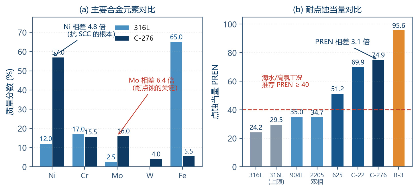
| Ni | 10.0 – 14.0 | Balance (-57) | Stabilizes austenite; resists reducing acids and chloride-induced SCC |
| Cr | 16.0 – 18.0 | 14.5 – 16.5 | Forms the passive film; resists oxidizing media |
| Mo | 2.0 – 3.0 | 15.0 – 17.0 | Key element for pitting / crevice corrosion resistance |
| W | — | 3.0 – 4.5 | Synergizes with Mo; improves localized corrosion resistance |
| Mn | ≤ 2.00 | ≤ 1.00 | Deoxidizer; austenite stabilizer |
| Si | ≤ 1.00 | ≤ 0.08 | Improves resistance to oxidizing acids (high-silicon cast iron principle) |
| C | ≤ 0.030 | ≤ 0.010 | Ultra-low carbon suppresses sensitization |
| N | ≤ 0.10 | — | Improves strength and pitting resistance |
| P | ≤ 0.045 | ≤ 0.025 | Impurity; harmful segregation |
| S | ≤ 0.030 | ≤ 0.010 | Impurity; sulfides trigger pitting |
| Co | — | ≤ 2.50 | Impurity control (semiconductor / nuclear industry concern) |
| V | — | ≤ 0.35 | — |
The compositions directly reveal three different design philosophies:
316L is a "chromium-based" design: Fe matrix; 16 – 18% Cr forms the passive film; Ni stabilizes austenite; Mo provides limited pitting resistance. Its advantages are low cost, good machinability and good performance in oxidizing media.
C-276 is a "nickel-chromium-molybdenum" ternary design: Ni matrix (57%), with 15.5% Cr and 16% Mo (6 – 8 times the molybdenum of 316L), plus 4% W. High Ni provides the fundamental safeguard against chloride-induced SCC; high Mo provides resistance to reducing acids and pitting.
Ultra-low carbon is a common requirement: 316L C ≤ 0.030% and C-276 C ≤ 0.010% both aim to suppress carbide precipitation (sensitization) during welding and heat treatment, avoiding intergranular corrosion.
2.2 Microstructure and Metallurgical Characteristics
| Item | 316L | C-276 | Engineering implication |
|---|---|---|---|
| Crystal structure | Face-centered cubic (FCC) austenite | Face-centered cubic (FCC) austenite | Both non-magnetic (magnetic drive pumps usable); no ductile-brittle transition |
| Stabilization method | Ni + N stabilize austenite | High Ni stabilizes austenite | C-276 microstructure is more stable |
| Typical inclusions | MnS, silicates, oxides | Sulfides, carbonitrides | Inclusions are preferred nucleation sites for pitting |
| Sensitization temperature range | 500 – 850 °C (Cr₂₃C₆ precipitation) | 550 – 1090 °C (µ phase, P phase, carbides) | C-276 should avoid long-term service at 550 – 1090 °C |
| Sensitization consequence | Cr depletion at grain boundaries → intergranular corrosion | Mo / Cr depletion at grain boundaries → intergranular corrosion | Weld heat-affected zone is the weak link |
| Post-weld treatment | Low carbon greatly reduces risk; thick plates still need solution annealing | Low-carbon design, but heat input must be controlled | See Ch. 6 |
| Work-hardening tendency | High | Extremely high | C-276 is difficult to machine; see 6.4 |
| Thermal conductivity (W/(m·K)) | 15 – 16 (room temperature) | 9 – 11 (room temperature) | Cutting heat dissipates harder in C-276 |
2.3 Pitting Resistance Equivalent Number (PREN)
PREN is an empirical index used to evaluate the pitting resistance of stainless steels and nickel-base alloys:
| Material | Cr (%) | Mo (%) | W (%) | N (%) | PREN | Relative to 316L |
|---|---|---|---|---|---|---|
| 316L | 16.5 | 2.1 | — | 0.05 | 24.2 | 1.0× |
| 316L (upper composition) | 18.0 | 3.0 | — | 0.10 | 29.5 | 1.2× |
| 904L | 20.0 | 4.3 | — | 0.05 | 35.0 | 1.4× |
| 254SMO (6Mo) | 20.0 | 6.1 | — | 0.20 | 43.4 | 1.8× |
| Duplex 2205 | 22.0 | 3.0 | — | 0.17 | 34.7 | 1.4× |
| Inconel 625 | 21.5 | 9.0 | — | — | 51.2 | 2.1× |
| Hastelloy C-276 | 15.5 | 16.0 | 4.0 | — | 74.9 | 3.1× |
| Hastelloy C-22 | 21.0 | 13.0 | 3.0 | — | 69.9 | 2.9× |
| Hastelloy B-3 | 1.5 | 28.5 | — | — | 95.6 | 3.9× |
| Titanium Gr.2 | — | — | — | — | ≥ 100 (different mechanism) | — |
| Zirconium Zr702 | — | — | — | — | ≥ 100 (different mechanism) | — |
Two points for a correct understanding of PREN:
PREN is a relative ranking tool, not an absolute life prediction. It is mainly used for lateral coMParison within the same material family (austenitic stainless steels / nickel-base alloys); it cannot be coMPared directly across categories (e.g., stainless steel vs. titanium).
PREN reflects only pitting / crevice corrosion resistance, not uniform corrosion or SCC resistance. C-276's high PREN comes from Mo, but high Mo is disadvantageous in oxidizing media — this is exactly the root of the nitric acid case in Section 4.3.
2.4 Mechanical Properties and Machining Cost
| Item | 316L | C-276 | Ratio |
|---|---|---|---|
| Density (g/cm³) | 7.98 | 8.89 | 1.11 |
| Yield strength R_p0.2 (MPa) | ≥ 170 | ≥ 355 | 2.09 |
| Tensile strength R_m (MPa) | 485 – 620 | 690 – 800 | 1.42 |
| Elongation A (%) | ≥ 40 | ≥ 40 | 1.0 |
| Hardness HB | ≤ 217 | ≤ 220 (solution annealed) | ≈ 1.0 |
| Thermal conductivity (W/(m·K)) | 15 – 16 | 9 – 11 | 0.68 |
| Coefficient of linear expansion (×10⁻⁶/K) | 16.0 | 11.2 | 0.70 |
| Elastic modulus (GPa) | 193 | 205 | 1.06 |
| Relative material price | 1.0 | 8 – 15 | — |
| Relative machining time | 1.0 | 2.5 – 4.0 | — |
| Relative pump cost | 1.0 | 2.5 – 4.0 | — |
It is worth noting that C-276's coefficient of linear expansion (11.2×10⁻⁶/K) is significantly lower than that of 316L (16.0×10⁻⁶/K). This is advantageous in high-temperature duty or in combination with ceramic / graphite parts — less thermal expansion mismatch.
3 Electrochemical Evaluation System
3.1 The Electrochemical Nature of Corrosion
All wet corrosion is an electrochemical process involving two conjugate reactions — anodic dissolution and cathodic depolarization:
When a metal is in the passive state, a dense oxide film forms on the surface and the anodic dissolution rate is suppressed by orders of magnitude. The essence of localized corrosion is the breakdown of the passive film at local sites while the rest of the surface remains passive, creating an unfavorable "small anode – large cathode" area ratio that drives extremely high local current density and leads to perforation.
3.2 Key Electrochemical Parameters
| Parameter | Symbol | Physical meaning | Engineering use | Method |
|---|---|---|---|---|
| Free corrosion potential | E_corr | Natural potential of the material in the medium | Judge thermodynamic corrosion tendency; coMPare with E_pit for safety | Open-circuit potential monitoring |
| Corrosion current density | i_corr | Corrosion rate extrapolated from polarization curves | Convert to annual corrosion rate (mm/y) | Tafel extrapolation / linear polarization |
| Pitting potential (breakdown potential) | E_pit (E_b) | Critical potential at which the passive film breaks down as potential rises | Core indicator of pitting resistance | Potentiodynamic polarization (ASTM G61) |
| Protection potential (repassivation potential) | E_prot (E_p) | Potential at which pits stop growing on the reverse scan | Judge whether existing pits continue to propagate | Cyclic polarization (ASTM G61) |
| Critical pitting temperature | CPT | Lowest temperature at which pitting occurs | Direct criterion for the service temperature ceiling | ASTM G48 C / G150 |
| Critical crevice corrosion temperature | CCT | Lowest temperature at which crevice corrosion occurs | Criterion for crevices (flanges, threads, gasket faces) | ASTM G48 B / D |
| Polarization resistance | R_p | Charge transfer resistance | Rapid coMParison of corrosion resistance | Linear polarization (ASTM G59) |
| Electrochemical impedance | Z | Frequency response of interfacial capacitance and resistance | Mechanism analysis, coating evaluation | EIS (ASTM G106) |
3.3 Cyclic Polarization Curves and the Hysteresis Loop
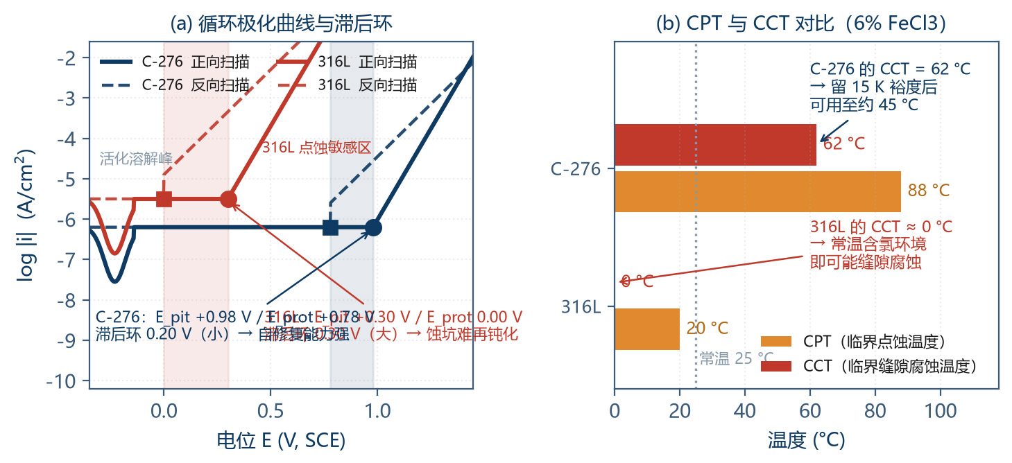
Cyclic polarization is the most powerful tool for evaluating localized corrosion. The scan starts below E_corr and proceeds in the positive direction; after the current surges (indicating pitting nucleation), scanning continues to a set value and then reverses.
A "hysteresis loop" forms between the forward and reverse scans, and its size directly reflects the localized corrosion susceptibility of the material:
| Hysteresis loop feature | E_prot vs. E_pit | Interpretation | Engineering meaning |
|---|---|---|---|
| No hysteresis loop | E_prot ≈ E_pit | No pitting, or immediate repassivation after pitting | Material is safe in this medium |
| Small hysteresis loop | E_prot slightly below E_pit | Low pitting susceptibility | Acceptable; some self-healing capability |
| Large hysteresis loop | E_prot far below E_pit | High pitting susceptibility; once nucleated, pits can hardly repassivate | Dangerous; avoid |
| No passive region | Current rises continuously | Material cannot passivate; active dissolution | Completely unsuitable |
This yields three safety criteria, which form the basis of all material selection conclusions in this paper:
E_corr < E_prot → safe (no nucleation; existing pits do not propagate)
E_prot < E_corr < E_pit → risk (no nucleation, but existing pits propagate)
E_corr > E_pit → dangerous (pits nucleate and propagate)
3.4 Test Methods and Standards
| Standard | Name | Method essentials | Output | Applicable to |
|---|---|---|---|---|
| ASTM G48 A | FeCl₃ pitting immersion test | 6% FeCl₃, 22 °C or 50 °C, 72 h immersion | Mass loss, pit depth, pit density | Rapid screening of stainless steels and nickel-base alloys (most common) |
| ASTM G48 B | FeCl₃ crevice corrosion test | Specimens with artificial crevices, 6% FeCl₃, 72 h | Mass loss and attack depth at crevices | Crevice corrosion susceptibility |
| ASTM G48 C | Critical pitting temperature CPT | 6% FeCl₃, programmed heating; temperature at current surge | CPT (°C) | Determine the temperature ceiling |
| ASTM G48 D | Critical crevice corrosion temperature CCT | Creviced specimens, 6% FeCl₃, programmed heating | CCT (°C) | Determine the temperature ceiling at crevices |
| ASTM G61 | Cyclic potentiodynamic polarization | Potentiodynamic scan + reverse scan | E_pit, E_prot, hysteresis loop | Quantitative pitting susceptibility evaluation |
| ASTM G150 | Electrochemical CPT test | Potentiostatic + programmed heating | CPT (°C) | More accurate than G48 C |
| ASTM G36 | Boiling MgCl₂ stress corrosion test | Boiling 42% MgCl₂ (-155 °C); U-bend or constant-load specimens | Time-to-cracking, crack morphology | Standard screening for chloride SCC of austenitic stainless steels |
| ASTM G28 A | Ferric sulfate – sulfuric acid test | Fe₂(SO₄)₃ + 50% H₂SO₄, boiling, 24 – 120 h | Uniform corrosion rate | Sensitization detection for nickel-base alloys |
| ASTM A262 E | Intergranular corrosion of stainless steels (Strauss test) | Copper sulfate – sulfuric acid + copper shot, boiling 15 h | Cracks after bending | Stainless steel sensitization detection |
| ASTM G5 | Potentiodynamic anodic polarization reference method | Standardized polarization measurement | Polarization curves | General method |
Recommendations on choosing test methods:
Rapid screening: ASTM G48 Method A (6% FeCl₃, 22 °C, 72 h). This is the fastest way to distinguish 316L from C-276 — 316L shows obvious pitting within hours, while C-276 usually shows no visible attack.
Determining the temperature ceiling: CPT and CCT. The design service temperature should be at least 15 – 20 K below CCT (CCT is usually 15 – 30 K lower than CPT, and crevices are nearly unavoidable in real structures).
SCC evaluation: ASTM G36 (boiling MgCl₂) applies to stainless steels; for nickel-base alloys, high-temperature autoclave tests or C-ring / U-bend immersion in the actual medium are more appropriate.
Final confirmation: coupon tests in the simulated actual medium (at least 500 h, recommended over 1000 h) — no standard test can replace this.
3.5 Electrochemical Parameter CoMParison of the Two Materials
| Parameter | Test condition | 316L | C-276 | Difference |
|---|---|---|---|---|
| E_corr (V, SCE) | 3.5% NaCl, 25 °C | −0.25 – −0.15 | −0.20 – −0.10 | Similar |
| E_pit (V, SCE) | 3.5% NaCl, 25 °C | +0.25 – +0.35 | +0.90 – +1.05 | +0.65 V |
| E_prot (V, SCE) | 3.5% NaCl, 25 °C | −0.05 – +0.05 | +0.70 – +0.85 | +0.75 V |
| Hysteresis loop width (V) | 3.5% NaCl, 25 °C | 0.30 – 0.40 | 0.15 – 0.20 | C-276 smaller |
| CPT (°C) | 6% FeCl₃ | 15 – 25 | > 85 | > 60 K |
| CCT (°C) | 6% FeCl₃ + crevice | ≈ 0 (even < 0) | 55 – 70 | > 55 K |
| i_corr (µA/cm²) | 3.5% NaCl, 25 °C | 0.1 – 0.5 | 0.02 – 0.08 | C-276 about 5× lower |
| R_p (kΩ·cm²) | 3.5% NaCl, 25 °C | 50 – 150 | 300 – 800 | C-276 about 5× higher |
| Passive film Cr/Fe ratio | AES / XPS surface analysis | 1.0 – 1.5 | 2.0 – 4.0 | C-276 richer in Cr / Mo |
| Boiling MgCl₂ SCC | ASTM G36, 155 °C | Cracks within hours | No cracking in 1000 h | Fundamental difference |
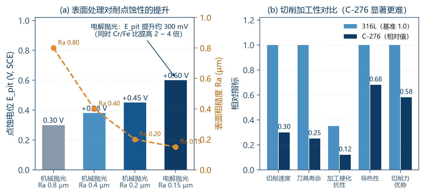
Note: the values are typical ranges; actual values are affected by surface condition (roughness, passivation treatment), medium composition (especially oxidizer content and pH), temperature and flow velocity. Improving surface roughness from Ra 0.8 µm to 0.2 µm can raise E_pit by 50 – 150 mV — precisely the value of the process control described in Ch. 6.
4 Quantitative CoMParison in Three Typical Acid Environments
4.1 Redox Classification of Acid Media
The first step in understanding acid corrosion is to classify acids by their redox characteristics. This determines whether the passive film can remain stable, and therefore which design — "high chromium" or "high molybdenum" — is more effective:
| Type | Representative media | Effect on passive film | Favorable elements | Effect on high Mo | Effect on high Cr |
|---|---|---|---|---|---|
| Reducing acids | HCl, dilute H₂SO₄, H₃PO₄, HF, organic acids | Destroy the passive film; active dissolution | Mo, Ni, W, Cu | Highly favorable (Mo stable under reducing conditions) | Unfavorable (Cr passive film dissolves) |
| Oxidizing acids | HNO₃, concentrated H₂SO₄ (> 93%), H₂CrO₄, HClO₄ | Promote and maintain the passive film | Cr, Si | Unfavorable (Mo → MoO₄²⁻ dissolves) | Highly favorable |
| Oxidizing + chloride | NaClO, FeCl₃, CuCl₂, wet Cl₂, HCl + oxidizers | Passive film locally broken down by Cl⁻; oxidizers raise the potential | High Cr + Mo + Ni | Favorable, but must be balanced with Cr | Favorable |
| Mixed / variable valence | H₂SO₄ + HNO₃, HCl + Fe³⁺, aqua regia | Varies with ratio and temperature; most complex | Requires specific evaluation | Requires specific evaluation | Requires specific evaluation |
This table is the hub of the entire material selection logic of this paper. It allows direct prediction:
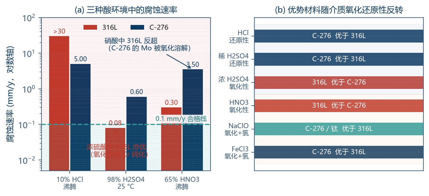
Hydrochloric acid (reducing) → 316L loses (the Cr-based passive film cannot be maintained); C-276 wins (high Mo);
Nitric acid (oxidizing) → 316L is actually superior (Cr passivation); C-276's high Mo becomes a burden;
Sodium hypochlorite (oxidizing + high chloride) → requires a balance of Cr and Mo; C-276 is far better than 316L, but titanium may be better still.
4.2 Hot Hydrochloric Acid Environment
Hydrochloric acid is one of the most difficult industrial acids: it is both a strongly reducing acid and a source of extremely high Cl⁻ concentration, simultaneously destroying the passive film and inducing pitting.
| Condition | 316L | C-276 | Verdict |
|---|---|---|---|
| 1% HCl, 25 °C | 0.5 – 1.5 | 0.01 – 0.05 | 316L unsuitable |
| 1% HCl, boiling (-100 °C) | > 10 (perforation) | 0.5 – 1.2 | 316L severe failure; C-276 marginal |
| 5% HCl, 25 °C | > 5 | 0.05 – 0.15 | 316L fails |
| 5% HCl, boiling | > 20 | 2 – 5 | C-276 also not for long-term use |
| 10% HCl, 25 °C | > 10 | 0.1 – 0.3 | C-276 usable |
| 20% HCl, 25 °C | > 15 | 0.3 – 0.8 | C-276 limited use |
| 20% HCl, boiling | > 30 | 3 – 8 | Neither material suitable |
| 37% HCl (concentrated), 25 °C | > 20 | 0.3 – 1.0 | C-276 usable (strict conditions) |
| 37% HCl, 60 °C | — | 1 – 3 | Not recommended |
| Hot HCl containing oxidizer (e.g., + 100 ppm Fe³⁺) | Fails | Fails | Key limitation of C-276 |
Correct material selection advice for hydrochloric acid duty:
Dilute cold HCl (< 10%, < 40 °C) → C-276 usable, but confirm the absence of oxidizers;
Hot or concentrated HCl → use Hastelloy B-3 (Ni-Mo system, Mo 28.5%), zirconium Zr702, tantalum, or PTFE/PFA lined pumps and all-plastic pump heads (PVDF/PP);
Semiconductor-grade HCl (high purity, extremely low metal ions) → PFA/PTFE all-plastic pump heads are the first choice, because any metal introduces ionic contamination.
4.3 Concentrated Sulfuric Acid Environment
Sulfuric acid corrosiveness varies strongly and nonlinearly with concentration — its biggest difference from hydrochloric acid: low concentrations are reducing, while high concentrations (> 93%) become oxidizing due to SO₃ formation.
| Concentration range | Characteristics | 316L (25 °C) | 316L (boiling) | C-276 (25 °C) | C-276 (boiling) | Recommended material |
|---|---|---|---|---|---|---|
| < 10% | Reducing | Usable (< 0.1) | Not usable | Excellent (< 0.05) | Fair (0.3 – 1) | C-276 / lined plastic |
| 10 – 40% | Reducing | Limited (0.1 – 0.5) | Not usable | Excellent (< 0.1) | Medium (1 – 3) | C-276 (temperature-limited) |
| 40 – 70% | Mainly reducing | Not usable | Not usable | Good (0.1 – 0.3) | Not usable (> 3) | C-276 (limit 60 °C) |
| 70 – 85% | Transition zone | Not usable | Not usable | Good (0.1 – 0.5) | Not usable | C-276 (limit 50 °C) |
| 85 – 93% | Transition zone | Not usable | Not usable | Good (0.1 – 0.3) | Limited | C-276 / 316L limited |
| 93 – 98% | Oxidizing | Usable (< 0.1) | Not usable | Medium (0.3 – 1.0) | Not usable | 316L / carbon steel / cast iron |
| > 100% (fuming) | Strongly oxidizing | Usable (< 0.5) | Not usable | Not usable | Not usable | 316L / carbon steel |
| Units: mm/y. Boiling temperature varies with concentration — about 330 °C at 98% and about 160 °C at 70%. | ||||||
The most noteworthy row in the table is 93 – 98% concentrated sulfuric acid:
In this range, the oxidizing nature of the acid lets 316L maintain passivation, with a corrosion rate < 0.1 mm/y — better than C-276 (0.3 – 1.0 mm/y in this range);
This is exactly why industry uses carbon steel or 316L tanks for concentrated sulfuric acid rather than expensive nickel-base alloys;
But note: concentrated sulfuric acid is extremely hygroscopic. If poor sealing or cleaning residue dilutes it (e.g., below 80%), 316L fails immediately. "Anti-dilution" design is therefore as important as material selection in concentrated sulfuric acid systems.
4.4 Concentrated Nitric Acid Environment: The Reversal of 316L
This is the most important and most counterintuitive section of this paper.
| Condition | 316L | C-276 | 304L | Aluminum | Verdict |
|---|---|---|---|---|---|
| 20% HNO₃, 25 °C | < 0.05 | 0.1 – 0.5 | < 0.05 | — | Stainless steel superior |
| 20% HNO₃, boiling | 0.1 – 0.5 | 1 – 3 | 0.1 – 0.5 | — | 316L superior |
| 65% HNO₃, 25 °C | < 0.05 | 0.3 – 1.0 | < 0.05 | < 0.1 | 316L superior |
| 65% HNO₃, boiling | 0.1 – 0.5 | > 3 | 0.1 – 0.5 | — | 316L markedly superior |
| Concentrated HNO₃ (> 90%) | 0.1 – 0.5 | Not usable | 0.1 – 0.5 | Usable | 316L superior |
| Fuming HNO₃ | 0.5 – 2 | Not usable | 0.5 – 2 | Usable | 316L usable |
| HNO₃ + HF (mixed acid) | Not usable | Limited | Not usable | Not usable | Need Monel / lined plastic |
Why is C-276 actually worse than 316L in nitric acid? The mechanism lies in:
The two-sidedness of molybdenum: Mo is extremely stable under reducing conditions and is the core pitting-resistance element. But under strongly oxidizing conditions, Mo is oxidized to soluble molybdate (MoO₄²⁻); the molybdenum-enriched surface layer loses its protection and corrosion is accelerated instead.
The disadvantage of nickel: Ni is less corrosion-resistant than Cr in nitric acid. The strong oxidizing nature forms a passive film dominated by Cr₂O₃, while the relative Cr content in the high-Ni matrix of C-276 (15.5%) is lower than in 316L (16.5%), and Mo also interferes with the coMPactness of the Cr passive film.
The role of silicon: 316L contains Si ≤ 1%, while C-276's Si is strictly limited to ≤ 0.08%. High silicon (e.g., 14.5% Si in high-silicon cast iron) is the key to nitric acid resistance; C-276 deliberately lowers Si to avoid intermetallic precipitation, at the cost of nitric acid resistance.
Engineering conclusion: nitric acid dosing systems should not blindly choose C-276. In HNO₃ below 65%, from ambient to boiling, 316L or 304L usually performs better and costs far less. Only when the nitric acid contains Cl⁻ or other reducing impurities should C-276 or C-22 be considered.
This also reminds us of a general material selection principle:
4.5 Selection Decision Tree for Acid Environments
| Decision step | Branch | Conclusion |
|---|---|---|
| ① Contains halides (Cl⁻, F⁻)? | No → ② / Yes → ⑤ | Halide ions are a necessary condition for localized corrosion |
| ② Medium oxidizing? | Strongly oxidizing (HNO₃, concentrated H₂SO₄) → ③ / Reducing (HCl, dilute H₂SO₄, organic acids) → ④ | — |
| ③ Oxidizing, no halides | Prefer 316L / 304L (low cost, good resistance) | C-276 not recommended |
| ④ Reducing, no halides | Low-temperature dilute acid → C-276 / hot concentrated acid → B-3 / zirconium / lined plastic | 316L only for dilute H₂SO₄ at room temperature |
| ⑤ Halides + oxidizing | (NaClO, FeCl₃, wet Cl₂) prefer C-276 / C-22; room-temperature NaClO may consider titanium or PVDF | 316L unsuitable |
| ⑥ Halides + reducing | (hot HCl) prefer B-3 / zirconium / PTFE lining | C-276 only for dilute cold, de-aerated conditions |
| ⑦ Contains F⁻ (HF, mixed acid) | All stainless steels and nickel-base alloys unsuitable; need Monel, Hastelloy C-2000 (limited) or all-plastic | — |
5 Three Major Localized Corrosion Modes in High-Chloride Environments
5.1 Pitting Corrosion
Pitting is the most common failure mode in dosing systems, especially in Cl⁻-containing media.
5.1.1 Mechanism: Autocatalytic Acidification
Pitting develops in two stages — nucleation and propagation:
Nucleation: Cl⁻ is small and highly penetrating. It adsorbs preferentially at passive film defects (inclusions, grain boundaries, dislocation emergences, mechanical scratches), forms soluble complexes with Cr³⁺, and thins the local passive film until perforation.
Propagation (autocatalytic): after film rupture, the pit interior metal dissolves rapidly (M → Mⁿ⁺ + n·e⁻); Cl⁻ migrates into the pit to maintain electroneutrality; metal cations hydrolyze:
The H⁺ produced by hydrolysis drops the pit interior pH to 1 – 2 (while the bulk solution may be near neutral); high acidity plus high Cl⁻ further accelerates dissolution — this is autocatalytic acidification, the fundamental reason pitting is hard to stop once nucleated.
Meanwhile, electrons conduct through the metal to the large cathodic area outside the pit (the passive surface) and are consumed by O₂ there, forming the unfavorable "small anode – large cathode" area ratio and driving extremely high pit current density.
5.1.2 Influencing Factors of Pitting
| Factor | Influence pattern | Quantitative relationship | Control measure |
|---|---|---|---|
| Cl⁻ concentration | Higher concentration lowers E_pit | E_pit = a − b·log[Cl⁻], b ≈ 0.05 – 0.12 V/decade | If the medium cannot be changed, change the material |
| Temperature | Higher temperature lowers E_pit; a CPT critical temperature exists | Basically no pitting below CPT | Control temperature < CCT − 15 K |
| pH | Acid promotes pitting; alkaline suppresses (pH > 10 significantly improves) | 316L pitting risk surges below pH 4 | Adjust pH with alkali (consider the process) |
| Oxidizers | Raise the potential → exceed E_pit → trigger pitting | Fe³⁺, Cu²⁺, dissolved oxygen all harmful | Deoxygenate; avoid Fe³⁺ contamination |
| Flow velocity | Low velocity / stagnation promotes pitting (crevices under deposits) | Velocity > 1.5 m/s significantly improves | Avoid dead zones; velocity ≥ 1.5 m/s |
| Surface roughness | Smaller Ra raises E_pit | Ra 0.8 → 0.2 µm: E_pit + 50 – 150 mV | Polishing + electropolishing (Ch. 6) |
| Surface contamination | Free iron and sulfide inclusions are pitting sources | — | Dedicated tools + acid pickling passivation |
| Alloying elements | Cr, Mo, N raise E_pit | PREN +10 ≈ CPT +10 – 15 K | Select high-PREN materials |
5.1.3 Pitting CoMParison: 316L vs. C-276
| Environment | [Cl⁻] | Temperature | 316L performance | C-276 performance |
|---|---|---|---|---|
| Tap water | -50 ppm | 25 °C | Basically safe (long-term risk remains) | Completely safe |
| Brackish water | -1000 ppm | 25 °C | At risk (especially with crevices / deposits) | Safe |
| Seawater | -19 000 ppm | 25 °C | Pitting + crevice corrosion inevitable | Safe |
| Seawater | -19 000 ppm | 50 °C | Severe failure | Safe (< CPT) |
| Salt spray | High | 35 °C | Surface rust spots | No change |
| 6% FeCl₃ (ASTM G48 A) | Extreme | 22 °C | Severe pitting within hours | No pitting in 720 h |
| 6% FeCl₃ | Extreme | 50 °C | Instantaneous perforation | Only slight attack or none |
| 10% NaClO | High + oxidizing | 25 °C | Pitting + crevice corrosion | Good |
| 20% NaClO | High + oxidizing | 25 °C | Severe failure | Usable (needs evaluation) |
| Wet Cl₂ gas | Extreme | Ambient | Not usable | Standard choice |
5.2 Crevice Corrosion
Crevice corrosion is extremely common in dosing systems because crevices are unavoidable inside a pump: flange faces, threads, bearing seat fits, under gaskets, O-ring grooves, and under deposits.
5.2.1 Mechanism: Differential Aeration Cell
The solution inside the crevice is stagnant and oxygen cannot be replenished. The process develops as follows:
1Initially, the oxygen reduction reaction is identical inside and outside the crevice;
2The crevice O₂ is consumed and oxygen reduction stops inside; outside (the large cathode), O₂ reduction continues;
3The crevice metal becomes the anode and dissolves (M → Mⁿ⁺ + n·e⁻);
4To balance the charge, Cl⁻ migrates into the crevice; metal ion hydrolysis produces H⁺;
5The crevice develops an aggressive high-Cl⁻, low-pH (down to pH 1) environment and corrosion accelerates.
This process is identical to the late-stage pitting mechanism. The difference is that crevice corrosion needs no induction period for passive film breakdown — the crevice geometry itself already provides the "occluded" condition. Therefore:
5.2.2 Quantitative CoMParison and Design Countermeasures
| Item | 316L | C-276 |
|---|---|---|
| CCT (ASTM G48 D, 6% FeCl₃) | ≈ 0 °C or lower | 55 – 70 °C |
| CCT in seawater | ≈ 0 – 5 °C (nearly inevitable) | > 50 °C |
| Critical Cl⁻ concentration (25 °C, with crevice) | -100 – 200 ppm | > 10 000 ppm |
| Crevice depth sensitivity | Most sensitive at depth 0.025 – 0.1 mm | Significantly improved |
| Typical failure locations | Flange faces, threads, under gaskets, shaft sleeve fits, under deposits | Only under extreme conditions |
| Engineering countermeasures | See the general measures below | See the general measures below |
General crevice corrosion countermeasures (apply to any material):
Eliminate crevices structurally: use welding instead of bolted joints (but grind welds smooth and perform PT inspection); use O-ring seals instead of flat gaskets;
Avoid stagnation zones: design flow paths without dead ends; minimize or shorten drain lines;
Use crevice-resistant gaskets: PTFE-clad gaskets are better than asbestos / rubber; spiral-wound metallic gaskets are better than non-metallic ones;
Control flow velocity: keep ≥ 1.5 m/s to prevent deposit buildup from forming "false crevices";
Clean periodically: remove scale and biofilm (the environment under biofilm is a typical crevice corrosion condition).
5.3 Stress Corrosion Cracking (SCC)
SCC is the most dangerous of the three localized corrosion modes because it gives no obvious warning — the material may look intact, yet suddenly cracks under stress far below the yield strength.
5.3.1 The Three Elements of SCC
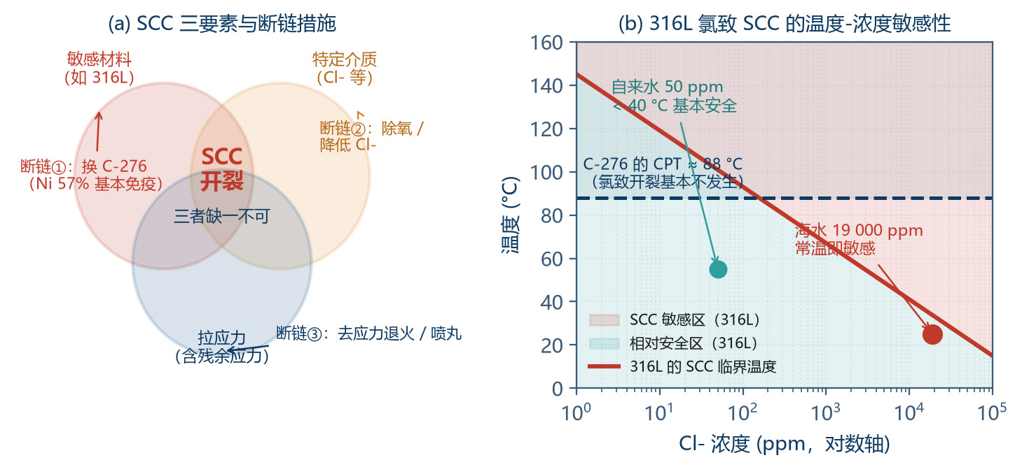
SCC occurs only when three conditions are simultaneously present:
| Element | Specifics | Chain-breaking measure |
|---|---|---|
| ① Susceptible material | 316L: highly susceptible to Cl⁻ SCC / C-276: excellent resistance | Switch to a high-Ni alloy (Ni > 30% is essentially immune), or duplex / ferritic steels |
| ② Specific medium | For 316L: Cl⁻, NaOH (caustic embrittlement), H₂S, polythionic acid | Reduce Cl⁻ concentration; control pH; deoxygenate; add inhibitors |
| ③ Tensile stress | Working stress + residual stress (welding, cold working, assembly) | Stress-relief annealing; shot peening to introduce surface compressive stress; lower the working stress |
5.3.2 Mechanism and Susceptibility of Chloride-Induced SCC
Chloride-induced SCC of austenitic stainless steels mainly follows the slip-dissolution mechanism:
1Tensile stress moves dislocations, creating slip steps on the surface that tear the passive film;
2The exposed metal dissolves rapidly in the corrosive medium;
3If repassivation is slower than dissolution, the crack advances; otherwise it passivates and stops;
4Stress concentration at the crack tip keeps the process going, forming transgranular or intergranular cracks.
Susceptibility rules for key parameters:
| Parameter | Susceptible range | Safe range | Notes |
|---|---|---|---|
| Temperature | 50 – 150 °C (peak 60 – 100 °C) | < 40 °C | Temperature is the strongest factor; rarely occurs below 40 °C |
| Cl⁻ concentration | > 10 ppm (very low levels suffice with oxygen) | < 1 ppm (strict) | With oxygen and stress concentration, tens of ppm can crack |
| pH | Acidic (pH 2 – 6) accelerates | pH > 10 significantly suppresses | Alkaline suppresses, but watch caustic embrittlement |
| Potential | E_corr in the susceptible potential zone | Cathodic protection below −0.8 V | Cathodic protection is effective |
| Stress level | > 0.3 – 0.5 × R_p0.2 | < 0.2 × R_p0.2 | Residual stress often far exceeds working stress |
| Dissolved oxygen | Oxygen significantly accelerates | Strict deoxygenation (< 20 ppb) suppresses | Boiler water is based on this principle |
| Cold working | Cold deformation > 10% significantly raises susceptibility | Avoid, or anneal | Bent tubes and stamped parts need annealing |
5.3.3 SCC CoMParison of the Two Materials
| Test / duty | 316L | C-276 | Notes |
|---|---|---|---|
| Boiling 42% MgCl₂ (ASTM G36, 155 °C) | Cracks within hours | No cracking in 1000 h | Standard screening test |
| High-temperature water with Cl⁻ (> 100 °C) | Highly susceptible | Essentially immune | Ni content is the key |
| Seawater (ambient – 60 °C, under stress) | Susceptible | Immune | — |
| NaOH caustic embrittlement (> 50 °C, > 20%) | Susceptible (> 60 °C) | Good resistance | Watch in caustic duty |
| Polythionic acid (hydrotreater shutdown) | Susceptible (sensitized) | Good resistance | Shutdown protection |
| H₂S acidic environment (NACE MR0175) | Must comply with standard limits | Compliant | — |
| High-temperature, high-pressure Cl⁻ autoclave | Cracks within days | No cracking for months | — |
| Ni content threshold for long-term safe use | Ni ≈ 10% insufficient | Ni ≈ 57% sufficient | Ni > 30% is essentially immune to chloride SCC |
6 Monoblock Precision Machining and Surface Integrity
6.1 Why Components Must Be Machined from Solid Billet
The traditional manufacturing routes for corrosion-resistant pump bodies are casting + machining, or welded structure + machining. In precision dosing, both routes have fundamental defects:
| Manufacturing route | Advantages | Defects | Effect on corrosion resistance |
|---|---|---|---|
| Sand casting + machining | Low cost; complex shapes possible | Porosity, shrinkage, inclusions; compositional segregation; inhomogeneous surface layer | Incomplete passive film at defects → pitting nucleation sites; reduced resistance in segregated zones |
| Investment (lost-wax) casting + machining | Better dimensional accuracy; acceptable surface quality | Still micro-shrinkage; high cost (especially C-276); defects in thick walls | Better than sand casting, but still inferior to forgings |
| Welded structure + machining | High material utilization; flexible | The weld is the preferred corrosion initiation site: segregation, sensitization, residual stress, geometric discontinuity | Intergranular corrosion in the weld HAZ; residual stress induces SCC; the most common failure cause of 316L pumps |
| Monoblock solid billet (forged / rolled) + 5-axis precision machining | Dense, defect-free structure; no welds; high dimensional accuracy; controllable surface quality | Low material utilization; long machining time; highest cost | Best overall: eliminates both risk sources (defects and residual stress); precisely controls roughness and surface integrity |
For precision dosing pumps, monoblock machining is also required by accuracy: the flow-path dimensions and gear cavity geometry of a dosing pump directly determine metering accuracy. The dimensional scatter of castings (usually ±0.5 – 1 mm) is far from sufficient, while machined parts can be held steadily to ±0.01 – 0.05 mm.
6.2 Process Route
| Step | Process content | Key control parameters | Quality control points |
|---|---|---|---|
| ① Billet preparation | Forging (open-die / closed-die) or rolled bar | C-276 forging temperature 950 – 1200 °C; 316L 900 – 1200 °C | UT inspection (defect-free); PMI spectral verification; grain size rating |
| ② Pre-heat treatment | Solution annealing | C-276: 1120 °C hold, then rapid water quench; 316L: 1050 – 1100 °C water quench | Hardness test; metallographic check (no precipitates) |
| ③ Rough machining | Remove 80% – 90% of the stock, leaving a uniform finishing allowance | Leave 0.5 – 1.0 mm | Avoid distortion from excessive cutting forces |
| ④ Stress relief | Remove rough-machining stress | 316L: 300 – 400 °C (stress relief) or re-solution annealing; C-276: avoid the 550 – 1090 °C sensitization zone, use low-temperature stress relief | Residual stress measurement (X-ray diffraction) |
| ⑤ Semi-finishing | Form to near-final dimensions | Leave 0.1 – 0.2 mm | Dimensional check |
| ⑥ Finishing / 5-axis machining | Flow path, gear cavity and seal faces formed in one clamping | Single clamping ensures geometric tolerances; form tools ensure flow-path surface accuracy | CMM full dimensional inspection; Ra inspection |
| ⑦ Surface treatment | Mechanical polishing → electropolishing → passivation | See 6.3 | Ra; surface composition (AES / XPS) |
| ⑧ Cleaning | Deionized water / solvent cleaning to remove metal ions and particles | Semiconductor grade: ultrapure water rinse to resistivity > 18 MΩ·cm | Particle count; ion chromatography |
| ⑨ Inspection | Dimensional + NDT + material + corrosion tests | — | PT / MT (surface), UT (internal); ASTM A262 E / G28 A intergranular corrosion tests; salt spray (sampling) |
| ⑩ Assembly | Cleanroom assembly with dedicated tools | Carbon steel tools strictly prohibited (iron contamination) | Iron contamination test (copper sulfate method) |
6.3 Surface Treatment: The Last Line of Defense for Corrosion Resistance
| Process | Principle | Ra improvement | Corrosion resistance improvement | Applicable materials |
|---|---|---|---|---|
| Mechanical polishing | Abrasives remove surface material in stages | Ra 0.8 → 0.2 – 0.4 µm | E_pit + 50 – 100 mV | Both |
| Electropolishing (EP) | Anodic selective dissolution; higher current density at micro-protrusions → leveling | Ra 0.8 → 0.1 – 0.2 µm | E_pit + 100 – 300 mV; surface Cr/Fe ratio up 2 – 4×; removes embedded iron and the damaged layer | Both (C-276 needs a special electrolyte) |
| Nitric acid passivation | Oxidizing acid dissolves surface free iron; promotes a Cr-rich passive film | No change to Ra | Removes free iron contamination; forms a dense Cr₂O₃ film | Standard for 316L (ASTM A967) |
| Citric acid passivation | Chelates free iron; environmentally friendly alternative | No change to Ra | Same as nitric acid passivation, safer | 316L (ASTM A967) |
| Electrochemical passivation | Forms a stable passive film at constant potential | No change to Ra | Denser, more uniform film | Common for C-276 |
| Shot peening | Introduces a surface compressive stress layer | Increases Ra (needs later polishing) | Suppresses SCC (compressive stress) | 316L (especially effective on welds) |
| Coatings (PVD / CVD) | TiN, CrN, DLC, etc. | Depends on the process | Improves wear and corrosion resistance, but must be pinhole-free | Special duty |
The mechanism of electropolishing deserves expansion:
Key process parameters (316L, phosphoric-sulfuric acid system):
| Parameter | 316L | C-276 |
|---|---|---|
| Electrolyte | H₃PO₄ : H₂SO₄ = 3:1 – 2:1 | Special formulation (with additives) |
| Temperature | 50 – 70 °C | 40 – 60 °C |
| Current density | 10 – 50 A/dm² | 15 – 40 A/dm² |
| Time | 2 – 10 min | 3 – 12 min |
| Cathode | Lead or stainless steel | Lead or titanium |
| Ra improvement | 0.8 → 0.1 – 0.2 µm | 0.8 → 0.15 – 0.3 µm |
| Surface Cr/Fe ratio | 1.2 → 2.5 – 4.0 | Significant Cr, Mo enrichment |
| E_pit improvement | +100 – 300 mV | +100 – 250 mV |
C-276 is a recognized difficult-to-machine material. Understanding its machining characteristics is essential for both cost and quality:
| Item | 316L | C-276 | Mechanism of C-276 difficulty |
|---|---|---|---|
| Relative machinability | 0.5 – 0.6 (free-cutting steel = 1.0) | 0.10 – 0.20 | — |
| Cutting speed Vc (carbide) | 80 – 150 m/min | 20 – 50 m/min | High hot strength; high cutting temperature; tool softening |
| Feed rate f | 0.1 – 0.3 mm/r | 0.08 – 0.20 mm/r | — |
| Depth of cut a_p | 1 – 5 mm | 0.5 – 3 mm | High cutting forces |
| Cutting force | Baseline | 1.4 – 1.8× | Hot strength + work hardening |
| Cutting temperature | Baseline | 30 – 50% higher | Thermal conductivity only 9 – 11 W/(m·K) |
| Work hardening | Significant | Extreme (surface hardness can rise 50 – 100%) | High austenite stability; strain-induced dislocations |
| Tool wear | Moderate | Severe (crater + flank wear) | Adhesion + diffusion wear |
| Chip form | Ribbon / segmented | Difficult to break; tangles | High toughness |
| Surface quality | Ra 0.4 easily achieved | Ra 0.4 needs fine process control | — |
| Recommended tools | Carbide K / P grades | Ultrafine-grain carbide (K grade), ceramic or CBN (finishing) | — |
| Tool life ratio | 1.0 | 0.15 – 0.35 | — |
Six essentials for machining C-276:
Keep cutting edges sharp: dull tools squeeze rather than cut, worsening work hardening and surface damage. Replace the tool when flank wear exceeds 0.2 mm.
Avoid feed pauses: pauses cause local work hardening, and the tool is shocked when cutting resumes.
Maintain continuous cutting: prefer climb milling to avoid repeatedly cutting the work-hardened layer.
Provide ample cooling: use cutting fluids with high extreme-pressure (EP) additives, flushed at high flow and high pressure (> 2 MPa).
Low speed, high feed: while protecting surface quality, prefer lower speed and higher feed to avoid repeated cutting on the work-hardened layer.
Sufficient rigidity: insufficient machine-tool-workpiece rigidity causes vibration, degrading surface quality and breaking tools.
6.5 Welding: If It Cannot Be Avoided
The primary purpose of monoblock machining is to avoid welding. However, in applications such as pipe connections, welding is still unavoidable.
| Item | 316L | C-276 |
|---|---|---|
| Welding method | TIG (preferred), MIG, plasma | GTAW / TIG (preferred), GMAW, SMAW (special filler required) |
| Filler metal | ER316L (C ≤ 0.03%) | ERNiCrMo-4 (matching wire) |
| Shielding gas | Ar (purity > 99.99%) or Ar + 2 – 5% N₂ | Ar (purity > 99.998%); back purge mandatory |
| Heat input control | 0.5 – 1.5 kJ/mm | 0.5 – 1.0 kJ/mm (stricter) |
| Interpass temperature | < 150 °C | < 100 °C |
| Sensitization risk zone | 500 – 850 °C | 550 – 1090 °C (wider) |
| Post-weld heat treatment | Usually not needed (low carbon); solution anneal for thick plates or sensitized conditions | Usually not needed (ultra-low carbon stabilized); but avoid service in the sensitization zone |
| Post-weld treatment | Grinding + acid pickling passivation | Grinding + acid pickling passivation (more critical) |
| Weld inspection | PT + RT (important welds) | PT + RT + intergranular corrosion test (G28 A) |
| Common defects | Hot cracks, intergranular corrosion | Hot cracks (high-Ni sensitive), porosity, intermetallic precipitation |
Table 6-6 Welding process essentials coMParison
7 Applications and Material Selection in Chemical Precision Dosing
7.1 Material Selection Matrix
| Medium | Concentration / temperature | 316L | C-276 | Better alternatives | Recommended |
|---|---|---|---|---|---|
| Sodium hypochlorite NaClO | 10 – 15% / < 40 °C | Not usable | Good | Titanium Gr.2, PVDF, PTFE | Titanium or PVDF |
| Sodium hypochlorite NaClO | < 5% / < 30 °C | Poor | Excellent | PVDF, PTFE | PVDF |
| Hydrochloric acid HCl | < 10% / < 40 °C (de-aerated) | Not usable | Good | PTFE lining, PVDF, B-3 | PTFE lining |
| Hydrochloric acid HCl | > 20% or > 60 °C | Not usable | Not usable | PTFE / PFA, zirconium, B-3 | PFA all-plastic |
| Sulfuric acid H₂SO₄ | < 40% / < 60 °C | Poor | Good | PTFE lining, Alloy 20 | C-276 |
| Sulfuric acid H₂SO₄ | 93 – 98% / < 40 °C | Excellent | Medium | Carbon steel, cast iron (room temperature) | 316L |
| Nitric acid HNO₃ | < 65% / < 60 °C | Excellent | Poor | 304L, aluminum (specific concentrations) | 316L / 304L |
| Nitric acid HNO₃ | > 65% or boiling | Good | Not usable | High-silicon cast iron, aluminum | 316L (limited conditions) |
| Hydrofluoric acid HF | Any | Not usable | Not usable | Monel 400, PTFE, PFA | PFA all-plastic |
| Ferric chloride FeCl₃ | 30 – 45% / < 50 °C | Not usable | Good | Titanium (limited concentration), PVDF | C-276 |
| Sodium hydroxide NaOH | < 50% / < 80 °C | Good (watch caustic embrittlement) | Good | Carbon steel (< 50 °C) | 316L / C-276 |
| Hydrogen peroxide H₂O₂ | 30 – 50% / < 50 °C | Poor (catalytic decomposition) | Medium | High-purity aluminum, PTFE, PVDF | PVDF / high-purity Al |
| Seawater / brine | Ambient – 50 °C | Not usable | Excellent | Titanium, Duplex 2205 | C-276 / titanium |
| Wet chlorine | Ambient | Not usable | Excellent | Titanium (limited moisture Cl₂) | C-276 |
| Ammonia water NH₃ | < 28% / ambient | Good | Good | Carbon steel (anhydrous ammonia) | 316L |
| CMP slurry | Alkaline / ambient – 50 °C | Medium (watch Cl⁻) | Excellent | PEEK, ceramics, high-purity PFA | C-276 / PEEK |
| High-purity electronic chemicals (SEMI grade) | Ambient | Poor (ion leaching) | Medium (ion leaching) | PFA, PTFE, high-purity PEEK | All-PFA flow path |
Three key points for reading this matrix:
C-276 is not a panacea: in the nitric acid and concentrated sulfuric acid ranges, 316L is actually better and far cheaper;
Plastics are often better: PTFE / PFA / PVDF outperform any metal in hydrochloric acid, hydrofluoric acid, hydrogen peroxide, sodium hypochlorite and similar media, at lower cost — an important trend in the dosing field;
Exclude metals for high-purity applications: in semiconductor-grade chemical dosing, any metal introduces ionic contamination; all-PFA / PTFE flow paths are mandatory.
7.2 Sodium Hypochlorite: The No.1 Challenge in Dosing
Sodium hypochlorite is the most common dosing medium in water treatment, disinfection and bleaching, and the medium with the most frequent pump failures. It deserves dedicated discussion.
Its aggressiveness comes from three superimposed corrosion factors:
High Cl⁻ concentration: 10% NaClO contains about 47 000 ppm Cl⁻ (2.5 times seawater);
Strong oxidizing power: the ClO⁻ standard potential E° = +0.89 V can raise the material potential into the transpassive region;
High pH (12 – 13): alkalinity suppresses pitting but promotes caustic embrittlement in some materials; NaClO decomposition also produces O₂, causing cavitation and gas-liquid two-phase flow.
| Material | 10% NaClO, 25 °C | 15% NaClO, 40 °C | Failure mode | Rating |
|---|---|---|---|---|
| 316L | Pitting within weeks | Fails within days | Pitting + crevice corrosion + SCC | Not usable |
| C-276 | Good (< 0.05 mm/y) | Usable (0.05 – 0.2 mm/y) | Pitting at high concentration / temperature | Usable |
| Titanium Gr.2 | Excellent (< 0.01 mm/y) | Excellent | Essentially no corrosion | Best metal |
| PVDF | Excellent | Good (< 60 °C) | Aging, swelling | Best non-metal |
| PTFE / PFA | Excellent | Excellent | Almost none | Best (but low strength) |
| Hastelloy C-2000 | Good | Good | — | Better than C-276 but higher cost |
| EPDM / fluororubber | Good (seals) | Medium | Aging | Common for seals |
Other engineering essentials for sodium hypochlorite systems:
Avoid metal-ion-catalyzed decomposition: Fe³⁺, Cu²⁺ and Ni²⁺ catalyze NaClO decomposition to produce O₂, causing cavitation and pressure fluctuation. No copper or iron components are allowed in the flow path.
Venting design: NaClO slowly decomposes and produces gas continuously; the pump inlet must have venting, or the pump will air-bind.
Avoid high temperature: the decomposition rate roughly doubles with every 10 K rise; above 40 °C, strengthen cooling and venting.
Shutdown flushing: flush with clean water before shutdown to prevent NaClO concentration and crystallization (the crystallized NaCl causes crevice corrosion and blockage).
7.3 Dosing System Design Essentials
| Element | Requirement | Reason | Common mistake |
|---|---|---|---|
| Filtration | Inlet filtration ≤ 25 µm (precision dosing ≤ 10 µm) | Particles cause wear and localized corrosion | Ignoring filtration; particles scratch the flow path and induce pitting |
| Venting | Inlet vent valve or automatic venting | NaClO, H₂O₂ and other media generate gas | Air binding causes unstable flow and cavitation |
| Backpressure valve | Outlet backpressure valve (0.1 – 0.3 MPa) | Stabilize flow, prevent siphoning and outlet pressure fluctuation | No backpressure valve; flow drifts significantly with downstream pressure |
| Pulsation damper | Mandatory for plunger / diaphragm pumps | Smooth pulsation; protect piping and instruments | Ignored; piping vibration and instrument damage |
| Safety valve | Outlet safety valve routed back | Prevent overpressure when the outlet is blocked | Safety valve venting directly to atmosphere (dangerous and wasteful) |
| Flushing / replacement | Flush with clean water or a coMPatible solvent before shutdown | Prevent crystallization, concentration and corrosion | Long shutdown without treatment; seizure on restart |
| Dry-run protection | Two-of-three interlock on level / flow / power | Dry running causes rapid damage | Relying on manual inspection only |
| Material marking | Pump body permanently marked with the material grade | Avoid misuse and mixing of materials | Marking lost or missing |
| Calibration | Gravimetric calibration every 3 – 6 months | Metering accuracy is the core dosing indicator | Never calibrated after installation |
| Spare parts | Stock critical wearing parts | Dosing interruption affects the process | No spares; long downtime after failure |
7.4 Ensuring Metering Accuracy
| Influencing factor | IMPact | Control measures |
|---|---|---|
| Medium viscosity change | Large (±5% – ±20%) | Constant temperature; viscosity feedforward compensation; gear pumps better than plunger pumps (insensitive to viscosity) |
| Backpressure fluctuation | Large (±3% – ±10%) | Backpressure valve; gear pumps less sensitive to pressure change than diaphragm pumps |
| Cavitation / gas generation | Extreme (can interrupt flow) | Inlet pressurization; venting; avoid negative-pressure suction |
| Particles and wear | Medium (long-term accumulation) | Filtration; wear-resistant materials; periodic calibration |
| Temperature | Medium (±1% – ±5%) | Constant temperature; temperature compensation |
| Pulsation | Small (for totalized volume) | Damper; low-pulsation pump types for instantaneous-flow-sensitive processes |
| Drive and control | Small (±0.1% – ±0.5%) | Servo drive + encoder; closed-loop gravimetric feedback |
8 Life-Cycle Cost and Selection Decisions
8.1 Cost Structure Analysis
| Cost item | 316L pump | C-276 pump | Notes |
|---|---|---|---|
| ① Initial purchase cost | 1.0 (baseline) | 2.5 – 4.0 | Material + machining difficulty |
| ② Installation & commissioning | 1.0 | 1.0 – 1.1 | Basically the same |
| ③ Planned maintenance | 1.0 | 0.5 – 0.7 | C-276 has a longer life and lower maintenance frequency |
| ④ Unplanned repair | High (frequent) | Low | Caused by failures |
| ⑤ Spare parts inventory | Medium | Low (but high unit price) | — |
| ⑥ Downtime loss | High | Low | Often the largest hidden cost |
| ⑦ Media loss / contamination | Medium – high | Low | Leakage and corrosion-product contamination |
| ⑧ Disposal | Low | Medium (precious metal recovery) | C-276 has residual value |
8.2 Typical Case Analysis
| Item | 316L plan | C-276 plan | Titanium Gr.2 plan |
|---|---|---|---|
| Initial investment (CNY) | 6 000 | 20 000 | 16 000 |
| Expected life (months) | 6 – 12 | 48 – 84 | 60 – 120 |
| Replacements in 10 years | 12 – 20 | 1.5 – 2.5 | 1 – 2 |
| 10-year replacement cost (CNY) | 72 000 – 120 000 | 30 000 – 50 000 | 16 000 – 32 000 |
| Downtime loss per event (CNY) | 3 000 | 3 000 | 3 000 |
| 10-year downtime loss (CNY) | 36 000 – 60 000 | 4 500 – 7 500 | 3 000 – 6 000 |
| 10-year maintenance cost (CNY) | 15 000 | 8 000 | 7 000 |
| 10-year LCC total (CNY) | 129 000 – 201 000 | 62 500 – 85 500 | 42 000 – 61 000 |
| Savings vs. 316L | Baseline | 39% – 52% | 62% – 70% |
| Payback period (months) | — | 8 – 14 | 6 – 11 |
Table 8-2 Case study: 10% sodium hypochlorite dosing (ambient temperature, continuous operation)
The case conclusions are clear:
Although C-276's initial investment is 3.3 times that of 316L, its 6 – 10 times longer life and greatly reduced downtime losses yield a payback period of only 8 – 14 months;
In this specific medium (sodium hypochlorite), the titanium Gr.2 plan has the lowest overall cost (about 30% lower than C-276), confirming the material selection advice in Section 7.2;
Downtime loss is often the largest hidden cost. In continuous chemical or water treatment plants, one unplanned shutdown can cost far more than the pump itself — which is why the value of high-reliability design is often underestimated.Fig. 8 - Placeholder: 10-year life-cycle cost coMParison
8.3 Selection Decision Process
| Step | Content | Output | Tool / method |
|---|---|---|---|
| ① Full medium composition analysis | Main components + impurities + oxidizers + halides + pH + temperature range | Complete medium specification sheet | Lab reports; pay special attention to trace impurities |
| ② Redox determination | Strongly oxidizing / reducing / mixed | Preliminary material family | Table 4-1 |
| ③ Halide risk assessment | Cl⁻, F⁻ concentration and temperature | Whether a high PREN is needed | Tables 5-1, 5-2 |
| ④ Preliminary candidate selection | 2 – 4 candidates | Candidate list | Table 7-1 selection matrix |
| ⑤ Electrochemical data check | CoMPare E_pit, CPT, CCT with the duty | Safety margin assessment | Table 3-4; ASTM G48 |
| ⑥ Coupon test confirmation | Actual medium, ≥ 500 h, including welds and the actual surface condition | Measured corrosion rates | Must not be skipped |
| ⑦ LCC coMParison | Initial investment + life + downtime loss | Cost-optimal plan | Tables 8-1, 8-2 |
| ⑧ Process and inspection definition | Monoblock machining + surface treatment + quality control specification | Technical agreement | Ch. 6 |
Table 8-3 Eight-step selection decision process
9 Conclusions and Outlook
9.1 Main Conclusions
Conclusion 1 (core principle of material selection): corrosion behavior depends strongly on the redox nature of the medium; no "comprehensively optimal" material exists. C-276 has overwhelming advantages in reducing media and chloride environments (PREN 74.9 vs. 24.2; CPT > 85 °C vs. 20 °C), but in concentrated nitric acid it is actually inferior to 316L — because Mo is oxidized to soluble molybdate under strong oxidizing conditions, and C-276 deliberately lowers Si (≤ 0.08%), sacrificing its resistance to oxidizing acids.
Conclusion 2 (electrochemical criteria): material selection should be based on the quantitative coMParison of five parameters — E_corr, E_pit, E_prot, CPT and CCT — with the criteria: E_corr < E_prot (safe), E_prot < E_corr < E_pit (risk), E_corr > E_pit (dangerous). The hysteresis loop width in cyclic polarization directly reflects the material's self-healing capability.
Conclusion 3 (three major localized corrosion modes): pitting is essentially autocatalytic acidification (pit pH drops to 1 – 2); the crevice corrosion CCT is usually 15 – 30 K below CPT, so design should use CCT with a 15 – 20 K margin; SCC requires all three elements — "susceptible material × specific medium × tensile stress" — simultaneously, and residual stress is the most easily overlooked driver, which is why stress relief and monoblock machining are crucial.
Conclusion 4 (manufacturing process): monoblock precision machining eliminates both risk sources (weld defects and residual stress); combined with electropolishing (E_pit +100 – 300 mV; surface Cr/Fe ratio up 2 – 4×), corrosion resistance improves markedly. C-276 is a difficult-to-machine material (relative machinability 0.10 – 0.20; tool life only 15% – 35% of 316L) and requires low speed, sharp tools and ample cooling.
Conclusion 5 (application selection): the optimal material for sodium hypochlorite dosing is titanium Gr.2 or PVDF, not C-276; hydrochloric acid, hydrofluoric acid, hydrogen peroxide and high-purity electronic chemicals should prefer all-plastic (PTFE / PFA / PVDF) solutions; C-276's main battlefield is chloride-containing reducing / oxidizing mixed media.
Conclusion 6 (economics): C-276's initial investment is 2.5 – 4 times that of 316L, but in typical corrosive duty the payback period is only 8 – 14 months, with a 10-year LCC saving of 39% – 52%. Downtime loss is the most underestimated cost item.
Conclusion 7 (the unskippable step): no standard test can replace coupon testing in the actual medium. Trace impurities (Fe³⁺, F⁻, organic solvents) can completely invalidate handbook data, while coupon testing costs only 2% – 5% of the pump price.
9.2 Technical Outlook
Higher-performance alloys: C-22 (Cr 21%, Mo 13%) balances oxidizing and reducing media better than C-276; C-2000 (Cu 1.6%) performs better in sulfuric and hydrochloric acid. As costs decline, these grades will expand their use in high-end dosing applications.
Surface modification technologies: laser cladding, plasma nitriding and PVD / CVD coatings can create high-corrosion-resistance surface layers on low-cost substrates — an important direction for reducing precious metal usage.
Additive manufacturing (3D printing): laser powder bed fusion (LPBF) of C-276 has reached engineering application, enabling conformal flow paths that conventional machining cannot produce; however, density, surface quality and residual stress must be solved.
Online corrosion monitoring: systems based on electrochemical noise (EN), linear polarization resistance (LPR) or electrical resistance (ER) probes can assess equipment corrosion in real time, shifting scheduled maintenance to condition-based maintenance.
Digital material selection platforms: fusing corrosion databases, electrochemical models and duty parameters into intelligent selection systems that automatically output candidate materials, expected life and LCC coMParisons can greatly reduce the material selection error rate.
Appendix A Symbols and Abbreviations
| Symbol / abbreviation | Meaning | Unit / notes |
|---|---|---|
| E_corr | Free corrosion potential | V (vs. reference electrode) |
| E_pit / E_b | Pitting potential / breakdown potential | V |
| E_prot / E_p | Protection potential / repassivation potential | V |
| i_corr | Free corrosion current density | µA/cm² |
| CPT | Critical pitting temperature | °C |
| CCT | Critical crevice corrosion temperature | °C |
| PREN | Pitting Resistance Equivalent Number | Dimensionless |
| SCC | Stress corrosion cracking | — |
| SCE | Saturated calomel reference electrode | E = +0.241 V (SHE) |
| SHE | Standard hydrogen electrode | Reference basis, E = 0 V |
| LPR | Linear polarization resistance | Ω·cm² |
| EIS | Electrochemical impedance spectroscopy | — |
| LPBF | Laser powder bed fusion (3D printing) | — |
| LCC | Life-cycle cost | CNY |
| mm/y | Millimeters per year (corrosion rate unit) | 1 mm/y ≈ 39.4 mpy |
| mpy | Mils per year (imperial corrosion rate unit) | 1 mpy = 0.0254 mm/y |
| UNS | Unified Numbering System (material grades) | S31603 / N10276 |
| PMI | Positive material identification (spectral analysis) | — |
| PT / MT / UT / RT | Penetrant / magnetic particle / ultrasonic / radiographic testing | — |
| EP | Electropolishing | — |
Appendix B Corrosion Rate Classification and Conversion
| Grade | Corrosion rate (mm/y) | Rating | Engineering action |
|---|---|---|---|
| A | < 0.05 | Excellent | Direct long-term use |
| B | 0.05 – 0.10 | Good | Long-term use; monitor |
| C | 0.10 – 0.50 | Acceptable | Non-critical parts; periodic thickness checks |
| D | 0.50 – 1.00 | Critical | Not recommended; short-term or easily replaceable parts only |
| E | 1.00 – 5.00 | Poor | Not recommended |
| F | > 5.00 | Completely unsuitable | Prohibited |
| Unit | mm/y | mpy | µm/y | g/(m²·h)* |
|---|---|---|---|---|
| 1 mm/y | 1 | 39.37 | 1000 | 0.114 |
| 1 mpy | 0.0254 | 1 | 25.4 | 0.0029 |
| 1 µm/y | 0.001 | 0.0394 | 1 | 0.000114 |
| *Converted for density 7.98 g/cm³ (316L) | ||||
Appendix C Standards and References
1ASTM G48 — Standard Test Methods for Pitting and Crevice Corrosion Resistance of Stainless Steels and Related Alloys by Use of Ferric Chloride Solution.
2ASTM G61 — Standard Test Method for Conducting Cyclic Potentiodynamic Polarization Measurements for Localized Corrosion Susceptibility.
3ASTM G150 — Standard Test Method for Electrochemical Critical Pitting Temperature Testing of Stainless Steels.
4ASTM G36 — Standard Practice for Evaluating Stress-Corrosion-Cracking Resistance of Metals and Alloys in a Boiling Magnesium Chloride Solution.
5ASTM G28 — Standard Test Methods for Detecting Susceptibility to Intergranular Corrosion in Wrought, Nickel-Rich, Chromium-Bearing Alloys.
6ASTM A262 — Standard Practices for Detecting Susceptibility to Intergranular Attack in Austenitic Stainless Steels.
7ASTM A967 — Standard Specification for Chemical Passivation Treatments for Stainless Steel Parts.
8ASTM G5 — Standard Reference Test Method for Making Potentiodynamic Anodic Polarization Measurements.
9NACE MR0175 / ISO 15156 — Petroleum and natural gas industries — Materials for use in H₂S-containing environments.
10ISO 17475 — Corrosion of metals and alloys — Electrochemical test methods — Guidelines for conducting potentiostatic and potentiodynamic polarization measurements.
11GB/T 4334 — Corrosion of metals and alloys — Intergranular corrosion test methods for stainless steels.
12GB/T 17897 — Test method for ferric chloride pitting corrosion of stainless steels.
13Haynes International. HASTELLOY C-276 alloy — Technical product handbook (composition, properties and corrosion data).
14NACE Corrosion Data Survey / DECHEMA Corrosion Handbook (corrosion data handbooks).
15Fontana, M. G. Corrosion Engineering (classic textbook on localized corrosion mechanisms).
16SEMI F57 / SEMI F78 — Specifications for materials in semiconductor wet chemical delivery systems.
Disclaimer and Contact
The corrosion data, electrochemical parameters and material selection advice in this white paper are compiled from public material handbooks, industry standards and corrosion data handbooks, and are provided for technical exchange and preliminary selection reference. Corrosion behavior is highly sensitive to the specific medium composition (especially trace impurities), temperature fluctuation, flow velocity, stress state and surface condition; the data herein cannot replace coupon testing and engineering evaluation for the actual duty.
Material selection decisions involve safety, environmental and economic factors. The methods and matrices provided in this white paper cannot replace the professional judgment of qualified corrosion and materials engineers. For applications involving hazardous chemicals, high temperature / pressure or continuous production plants, complete the coupon testing and comply with relevant industry standards and regulations.
Material prices and machining costs fluctuate with the market; the relative cost relationships herein are for reference only — obtain current quotations for actual procurement.
The technical content of this white paper may be revised as products evolve and research results update, without prior notice. For the latest version, technical specifications for specific materials, or material selection evaluation and coupon testing support for specific media, please contact the JONSN Precision Fluid Technology Center.