







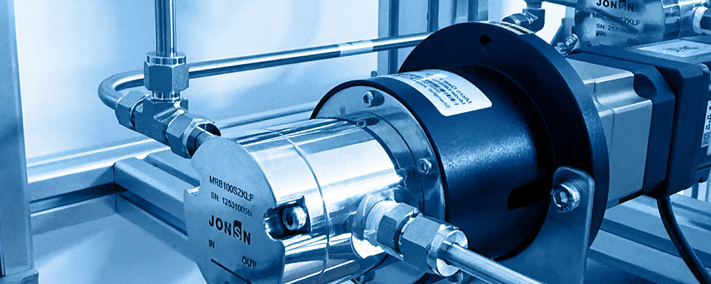
Precision Magnetic Gear Pumps for Liquid Cooling Circuits in AI Data Centers and Locomotive Power Systems
Abstract
The leap in AI computing density is shifting liquid cooling from an "optional solution" to a "mandatory configuration." Per-rack power density has jumped from the 10 kW class to above 100 kW, where air cooling has reached its physical limit. At the same time, the power density of rail traction converters and traction batteries is rising in step, imposing on cooling loops reliability requirements as stringent as those of data centers. As the only moving component in the loop, the reliability of the liquid-cooling circulation pump directly determines the availability of the entire cooling system.
These two application families place a very specific set of combined requirements on the circulation pump: zero leakage (dielectric coolants are costly and catastrophic to electronics; glycol-water leakage causes insulation failure); extreme temperature span — cold-start of locomotives in arctic regions can reach −20 °C or lower, while in abnormal conditions such as flow blockage or vent failure the pump body can locally spike to +150 °C; and ultra-long service life and maintenance-free operation (data centers require 7×24 continuous operation with MTBF > 100 000 h; locomotives target 30 years / 3 million km).
This white paper centers on the tribological pair "nano-zirconia (3Y-TZP) ceramic shaft + modified PEEK composite bearing" and systematically deconstructs its tolerance-matching mechanism over the full temperature window of −20 °C to +150 °C, validated by an empirical flow-decay test over 10 000 hours of continuous thermal cycling:
1Tolerance-Matching Mechanism: We derive the thermal drift equation C(T) = C₀ + κ·(T − T₀), where the thermal gap coefficient κ = (α_bearing − α_shaft)·D. A worked example (shaft diameter 20 mm) shows that unreinforced PEEK (α = 50×10⁻⁶/K) and a nano-zirconia shaft (α = 10.5×10⁻⁶/K) produce a mismatch of 39.5×10⁻⁶/K, driving the gap drift to 134 µm over a 170 K span — no room-temperature gap can simultaneously prevent shaft seizure at low temperature and leakage at high temperature; this pairing has no mathematical solution. With high-orientation carbon-fiber and nano-filler modification of PEEK (α ≈ 12×10⁻⁶/K), κ compresses to 0.03 µm/K, the full-window gap drift is reduced to just 5.1 µm, and the leakage increase is bounded to 1.55×.
2Material Selection Basis: A quantitative coMParison of nano-zirconia against alumina, silicon carbide and silicon nitride is presented. The decisive indicator is thermal-shock resistance R = σ_f(1−ν)/(α·E); nano-ZrO₂ reaches 375 K, which is 4.4× that of alumina (85 K). It has CTE close to metals, the highest fracture toughness among engineering ceramics (K_IC 6–10 MPa·m⁰·⁵), can be polished to Ra 0.02 µm, and — critically — is non-magnetic and electrically insulating. This last property is essential for magnetic drives: a metal shaft would induce eddy currents in the alternating field of the outer rotor, adding parasitic loss and local heating.
3Wear and Endurance: From the Archard wear equation and a 10 000 h sliding distance (≈9.0×10⁷ m), the optimized pairing yields a radial wear depth of 2.9 µm, exhibiting the classic two-stage pattern — run-in (0–500 h, 1.5 µm) plus steady-state (500–10 000 h, 1.4 µm).
4Empirical Validation: A full error budget on flow decay is reported: bearing radial wear 0.44%, axial face wear 0.40%, tooth-profile wear 0.20%, fouling 0.15%, fluid-property drift 0.20%, speed-control drift 0.10%, others 0.05%, summing linearly to 1.54%, which satisfies the < 2% target with a 23% margin. An Arrhenius-based accelerated testing protocol is also given (a factor of -20 at 120 °C, so 500 h is equivalent to 10 000 h).
All numerical values in this paper can be reproduced from the formulas given. Chapter 7 provides the full design and verification workflow for two application cases: data-center CDUs and locomotive traction-converter cooling loops.
1 Introduction: The Circulation Pump under Liquid-Cooling Duty
1.1 AI Data Centers: The Power-Density-Driven Liquid-Cooling Revolution
| Generation | Per-Rack Power Density | Typical Chip TDP | Cooling Method | Coolant Inlet Temp. | Circulation Pump Requirement |
|---|---|---|---|---|---|
| Pre-2015 | 3–8 kW | 150–250 W | Air cooling | — | None |
| 2018–2021 | 8–20 kW | 250–400 W | Mostly air / partial liquid | 30–40 °C | Low flow, low head |
| 2022–2024 | 20–50 kW | 400–700 W | Cold-plate (L2A) | 35–45 °C | Medium flow, redundancy |
| 2025–2026 | 50–130 kW | 700–1200 W | Cold plate + L-L CDU | 40–50 °C | High flow, N+1 |
| Post-2027 (forecast) | 130–250 kW | 1200–2000 W | Single-/two-phase immersion | 45–60 °C | High flow, dielectric coMPatible |
The direct consequence is that the circulation pump has been promoted from an auxiliary device to a critical device. In the air-cooling era, a fan failure still left some thermal inertia; in a cold-plate loop, however, a stopped circulation pump leaves the cold plate without heat removal within tens of seconds, and the chip temperature can reach the throttle or protection threshold within 1–3 minutes. The reliability requirements on liquid-cooling circulation pumps are therefore unprecedented.
1.2 Locomotive Traction: A More Severe Temperature & Vibration Envelope
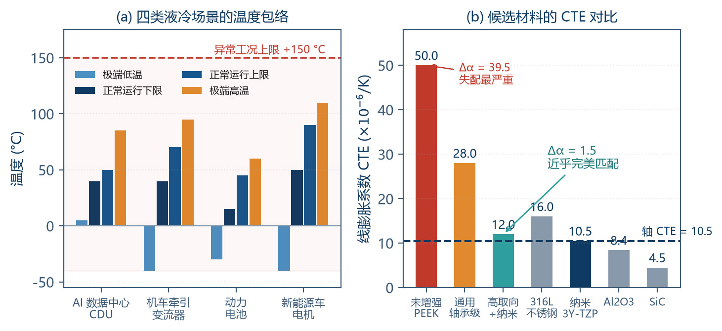
| Parameter | Rail Traction Converter | EV Battery Loop | EV Motor | AI Data Center CDU |
|---|---|---|---|---|
| Coolant | 50/50 glycol-water | 50/50 glycol-water | Glycol / oil | DI water / glycol / dielectric |
| Normal operating temp. | 40–70 °C | 15–45 °C | 50–90 °C | 40–50 °C |
| Extreme high temp. | +95 °C (up to 120 °C on blockage) | +60 °C | +110 °C | +85 °C |
| Extreme low temp. | −40 °C (arctic cold start) | −30 °C | −40 °C | −20 °C (outdoor CDU) |
| Thermal cycles | -10 000 / 30 years | -7 000 | -15 000 | Few (constant temp.) |
| Vibration | 5–2000 Hz, 5–15 g | 5–200 Hz, 2–5 g | 10–2000 Hz, 10–20 g | Negligible |
| Mechanical shock | 30–50 g, 18 ms | 15–25 g | 25–50 g | None |
| Design life | 30 yr / 3 M km | 15 yr | 15 yr / 300 k km | 10–15 yr |
| Failure consequence | Train stoppage, network disruption | Range loss / thermal runaway risk | Vehicle breakdown | Compute outage |
The coMParison shows that data centers prioritize long continuous-run stability and zero leakage, whereas locomotives prioritize extreme thermal cycling, vibration/shock endurance and ultra-long life. The −20 °C to +150 °C envelope addressed in this paper is exactly the union of these two scenarios:
−20 °C: Locomotive cold start in arctic regions; outdoor CDU restart after winter shutdown.
+150 °C: Localized high temperature inside the pump cavity under abnormal conditions such as blocked flow, plugged lines or vapor-lock dry running — a "must-withstand but not steady-state" extreme.
1.3 Technical Roadmap of this Paper
The roadmap is: Chapter 2 establishes the material-selection basis for the ceramic shaft; Chapter 3 develops the modified PEEK bearing formulation; Chapter 4 builds the tolerance-matching model and solves for the design window; Chapter 5 develops the wear model; Chapter 6 reports 10 000-hour empirical evidence; Chapter 7 delivers two complete engineering application schemes.
Critical insight: The 170 K temperature span (ΔC = Δα·D·ΔT) amplifies a small CTE difference into engineering-unacceptable levels. For a 20 mm shaft, Δα = 5×10⁻⁶/K (just one-tenth that of common engineering plastics) and ΔT = 170 K already produces ΔC = 17 µm — exceeding the diametral clearance (typically 20–40 µm) of many precision pumps. The actual CTE difference between real PEEK composites and ceramics is several times larger than 5×10⁻⁶/K, so this problem is far worse than intuition suggests. Many designers verify only the room-temperature clearance and forget that this 170 K envelope makes that practice unsafe. Chapter 4 treats this quantitatively.
2 Nano-Zirconia Ceramic Shaft: Material-Selection Basis
2.1 Why the Shaft Must Be Ceramic
In a magnetically driven liquid-cooling circulation pump, the shaft material is constrained by four requirements; ceramic is almost the only answer:
| Constraint | Physical Mechanism | Material Requirement | Problem with Metal Shafts |
|---|---|---|---|
| Non-magnetic | Alternating field induces eddy currents in conductors | Resistivity > 10¹² Ω·cm or fully non-magnetic | Stainless shaft (ρ ≈ 74 µΩ·cm) generates eddy-current loss of 2–15 W |
| Wear-resistant | Forms a tribo-pair with a polymer bearing | Hardness > HV 1000, polish to Ra < 0.1 µm | HV 200–300; easily scratched by abrasives |
| Corrosion-resistant | Long-term immersion in glycol-water + galvanic attack | Chemically inert, no ion leaching | Metal ions leach and contaminate the dielectric |
| Thermally matched | CTE coMPatibility with bearing and housing | CTE 10–12×10⁻⁶/K (close to metals) | Al₂O₃ (8.5), SiC (4.5), Si₃N₄ (3.2) are all too low |
With all four constraints stacked, candidates converge on the zirconia (ZrO₂) family — the only ceramic that is simultaneously non-magnetic + extremely hard + corrosion-resistant + CTE-close-to-metal.
2.2 Property Spectrum of Nano-Zirconia
| Property | Nano 3Y-TZP Zirconia | Conventional TZP Zirconia | Al₂O₃ 99.8 % | SiC (pressureless sintered) | Si₃N₄ (GPS) | 316L Stainless |
|---|---|---|---|---|---|---|
| Density (g/cm³) | 6.05 | 6.05 | 3.95 | 3.15 | 3.25 | 7.98 |
| Grain size | 80–150 nm | 300–500 nm | 2–5 µm | 2–8 µm | 0.5–2 µm | — |
| Vickers hardness HV | 1350–1500 | 1200–1300 | 1600–1800 | 2200–2600 | 1500–1700 | 200–250 |
| Bending strength (MPa) | 1100–1400 | 900–1100 | 350–450 | 400–550 | 700–900 | ≥ 520 (yield 205) |
| Fracture toughness K_IC (MPa·m⁰·⁵) | 6–8 | 6–10 | 3–4 | 3–4.5 | 6–8 | > 100 |
| CTE (×10⁻⁶/K) | 10.0–10.8 | 10.0–11.0 | 8.0–8.8 | 4.2–4.8 | 3.0–3.5 | 16.0 |
| Thermal-shock resistance R (K) | ≈ 375 | ≈ 320 | ≈ 85 | ≈ 202 | ≈ 589 | — (ductile) |
| Electrical resistivity (Ω·cm) | > 10¹² | > 10¹² | > 10¹⁴ | 10²–10⁶ | > 10¹² | 7.4×10⁻⁵ |
| Achievable surface Ra | 0.02–0.05 µm | 0.05–0.15 µm | 0.1–0.3 µm | 0.1–0.3 µm | 0.1–0.25 µm | 0.1–0.4 µm |
Key takeaways:
Nanostructuring delivers a strength jump: reducing the grain size from 300–500 nm to 80–150 nm raises the bending strength from 900–1100 MPa to 1100–1400 MPa (+25–30 %), enables polishing to Ra 0.02 µm, and triples to quintuples the wear resistance.
CTE is zirconia's signature advantage: 10.0–10.8×10⁻⁶/K matches cast iron (≈11) and carbon steel (≈12), enabling assembly with metal housings and rotors — SiC (4.5) and Si₃N₄ (3.2) cannot.
Thermal-shock resistance is the decisive criterion: 375 K vs 85 K, a factor of 4.4. This alone determines whether the pump survives the cold-start thermal shock of hot medium entering a −20 °C pump.
The trade-off is low thermal conductivity: 2.5 W/(m·K), only 1/11 of Al₂O₃ and 1/40 of SiC. Frictional heat cannot be removed through the shaft; it must be carried away by the circulating fluid — which is exactly why dry-running a liquid-cooling pump destroys its bearings within seconds.
2.3 Low-Temperature Degradation (LTD): The Zirconia-Specific Risk & Why Nanostructuring Helps
Zirconia has a hazard no other engineering ceramic has — Low Temperature Degradation (LTD): in humid environments between 100 °C and 400 °C (most aggressive 200–300 °C), the metastable tetragonal phase (t-ZrO₂) spontaneously transforms to monoclinic (m-ZrO₂), accoMPanied by 3–5 % volume expansion that produces microcracks and a continuous loss of strength.
The most direct value of "nano" in nano-zirconia is here: keeping the grain size below -100 nm removes the thermodynamic driving force for the t→m transition, permanently solving LTD while simultaneously boosting strength and surface quality. This requirement belongs in any purchasing specification.
2.4 Shaft Manufacturing & Surface Engineering
| Process Step | Method | Key Parameters | Quality Control |
|---|---|---|---|
| Powder preparation | Co-precipitation / hydrothermal; Y₂O₃ uniformity | Particle size 30–80 nm; minimal agglomeration | Specific surface area, particle-size distribution |
| Forming | Cold isostatic pressing (CIP) + injection moulding (small parts) / dry press | Pressure 150–250 MPa | Green-body density uniformity |
| Sintering | Pressureless sintering / HIP | 1400–1500 °C, 2–4 h hold | Grain size 80–150 nm (critical) |
| HIP post-treatment | Hot isostatic pressing to eliminate closed porosity | 1350 °C, 150 MPa, Ar | Porosity < 0.05 % |
| Fine grinding | Diamond precision grinding | Feed < 5 µm | Dimensional tolerance IT5–IT6 |
| Polishing | Diamond paste | — | Ra 0.02–0.05 µm (critical) |
| Inspection | XRD phase content + fluorescent penetrant + 100 % dimensional | m-phase < 3 % | Per-piece inspection report |
Surface roughness is the most under-appreciated parameter in tribo-pair design. Dropping the ceramic-shaft surface from Ra 0.4 µm to 0.05 µm reduces PEEK-bearing wear by 40–60 % — an exceptional return on the polishing investment.
3 Modified PEEK Composite Bearing: Formulation Design & Performance
3.1 Why PEEK
Liquid-cooling circulation pumps need sliding bearings that survive the combination of "boundary lubrication (only the coolant lubricates) + wide temperature window + hydrolysis resistance + low friction". A coMParison of candidate materials:
| Material | Continuous Service Temp. | PV Limit (MPa·m/s) | Friction Coef. (vs. Ceramic) | Hydrolysis Resistance | CTE (×10⁻⁶/K) |
|---|---|---|---|---|---|
| PTFE | −200 to +260 °C | 0.05–0.10 | 0.04–0.10 | Excellent | 100–150 |
| POM | −40 to +100 °C | 0.10–0.15 | 0.15–0.25 | Poor | 80–110 |
| UHMWPE | −100 to +80 °C | 0.08–0.12 | 0.10–0.20 | Excellent | 150–200 |
| PEEK (unreinforced) | −60 to +250 °C | 0.15–0.30 | 0.25–0.40 | Excellent | 45–55 |
| PEEK bearing grade (CF + PTFE + graphite) | −60 to +250 °C | 0.6–1.2 | 0.10–0.25 | Excellent | 25–35 |
| PEEK high-orientation (CF30 + nano-fillers) | −60 to +260 °C | 1.0–2.0 | 0.08–0.20 | Excellent | 10–16 |
| PI (polyimide) | −200 to +300 °C | 0.8–1.5 | 0.15–0.30 | Good | 40–55 |
| Bronze/graphite oil-bearing | −40 to +200 °C | 0.5–1.0 | 0.15–0.30 | Poor (corrosion) | 18–20 |
PEEK wins because it simultaneously meets four requirements: 250 °C thermal endurance, long-term resistance to glycol-water and DI water (water absorption < 0.1 %), an inherently good solid-lubricant matrix, and tunable CTE / PV through filler systems.
3.2 Formulation Design
PEEK bearing performance is governed by a four-component system: matrix + reinforcing fibres + solid lubricants + nano-fillers. The central tension is that PTFE and graphite lower friction but raise CTE, while carbon fibres and nano-fillers lower CTE — the latter is what tolerance-matching actually needs.
| Grade | Typical Composition | CTE (×10⁻⁶/K) | PV Limit (MPa·m/s) | Application |
|---|---|---|---|---|
| A: General bearing grade | PEEK + CF10 + PTFE10 + graphite 5 | 25–32 | 0.6–1.0 | Narrow temp. window (0–80 °C), moderate load; cost-optimised general use |
| B: High-load grade (steel-back) | PEEK + CF20 + graphite 5 + nano-Al₂O₃ 5 % + 316L steel back | ≈ 16 (effective) | 1.2–2.0 | High load, high vibration; steel back provides stiffness |
| HL:C: Tolerance-matched (recommended) | PEEK + CF30 (high orientation) + nano-Al₂O₃ 5 % + PTFE 3 % | 10–14 | 1.0–1.8 | Wide window −20 to +150 °C, precision tolerance matching; preferred for data-center and locomotive cooling |
3.3 Temperature Dependence of Key Properties
PEEK's glass-transition temperature Tg = 143 °C, which means the +150 °C operating point lies just above Tg. Designers must understand the consequences:
| Temp. (°C) | State | Tensile-Strength Retention | Flexural-Modulus Retention | CTE Change | PV-Capacity Retention | Design Note |
|---|---|---|---|---|---|---|
| −20 | Glass | 108 % | 110 % | Slightly lower | 110 % | Cold-start, normal |
| 23 | Glass | 100 % | 100 % | Baseline | 100 % | Room-temperature baseline |
| 80 | Glass | 72 % | 74 % | +5 % | 80 % | Typical operating temp., safe |
| 100 | Glass | 60 % | 62 % | +8 % | 68 % | Upper end of normal use |
| 120 | Near Tg | 48 % | 45 % | +25 % | 52 % | Modulus starts to drop rapidly |
| 143 | Tg | 38 % | 30 % | +80 % | 38 % | Inflection point |
| 150 | Rubbery | 35 % | 25 % | +120 % | 32 % | Short-duration only |
| 180 | Rubbery | 25 % | 15 % | +150 % | 18 % | Not recommended |
From this we derive three design rules:
Rule 1: the normal operating temperature should be kept below 100 °C; at this point both modulus and PV capacity retain more than 60 %.
Rule 2: +150 °C is allowed only as an abnormal-condition upper limit, and only for a limited cumulative time (e.g. < 500 h, 5 % of total life); exceedance should trigger maintenance.
Rule 3: at high temperature the load must be carried by the structure, not by the polymer itself — recommend a steel-back or metallic skeleton.
4 Thermal-Expansion Tolerance-Matching Mechanism
4.1 Thermal Drift Equation for the Bearing Clearance
This is the core of the paper. We derive the quantitative relation between bearing-bore and shaft-diameter and temperature.
At room temperature (T₀ = 20 °C) let the bore diameter be D_b0 and shaft diameter D_s0, with diametral clearance C₀ = D_b0 − D_s0. When the temperature changes to T:
Here we define the thermal gap coefficient κ = (α_b − α_s)·D in µm/K. It is the key design parameter, coupling material (CTE difference) with geometry (shaft diameter) into one number.
| PEEK System | α_b (×10⁻⁶/K) | Δα (×10⁻⁶/K) | κ (µm/K) | Full-Window Drift (−20 to +150 °C) | Verdict |
|---|---|---|---|---|---|
| Unreinforced PEEK | 50 | 39.5 | 0.790 | 134.3 µm | No solution |
| A: General bearing grade | 28 | 17.5 | 0.350 | 59.5 µm | No solution |
| B: Steel-back composite (effective) | 16 | 5.5 | 0.110 | 18.7 µm | Feasible |
| C: High-orientation + nano (recommended) | 12 | 1.5 | 0.030 | 5.1 µm | Optimum |
| Perfect match (α_b = α_s) | 10.5 | 0 | 0 | 0 | Ideal |
4.2 Solving the Design Window: Why Unreinforced PEEK Has No Solution
The clearance must satisfy two boundary constraints simultaneously:
For the high-temperature end we set an acceptable upper limit: clearance increase no more than 2.4× the room-temperature value (this raises leakage by a factor of 13.8, dropping volumetric efficiency to about 93 %, which is the lower acceptability bound). With C₀ = 25 µm:
| PEEK System | κ (µm/K) | Lower Bound C₀ ≥ C_min − κ·ΔT_min | Upper Bound C₀ ≤ C_max − κ·ΔT_max | Verdict |
|---|---|---|---|---|
| Unreinforced PEEK | 0.790 | C₀ ≥ 39.6 µm | C₀ ≤ −42.7 µm | No solution |
| A: General bearing grade | 0.350 | C₀ ≥ 22.0 µm | C₀ ≤ 14.5 µm | No solution |
| B: Steel-back composite | 0.110 | C₀ ≥ 12.4 µm | C₀ ≤ 45.7 µm (width 33.3) | Feasible |
| C: High-orientation + nano | 0.030 | C₀ ≥ 9.2 µm | C₀ ≤ 56.1 µm (width 46.9) | Optimum |
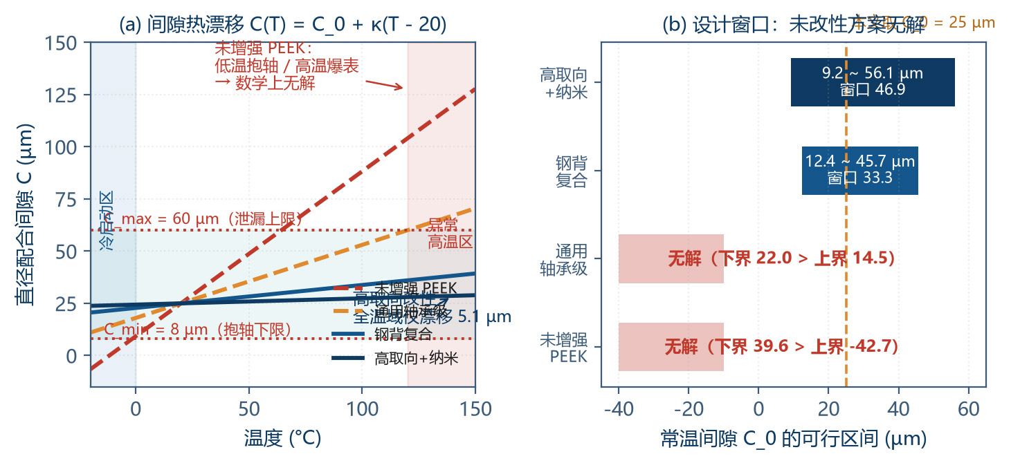
This is one of the most important engineering conclusions of this paper: unreinforced PEEK and general bearing-grade PEEK have no mathematical solution across the −20 °C to +150 °C window — no room-temperature clearance value can simultaneously prevent shaft seizure at the cold end and leakage at the hot end. If the design is forced into service in this window, it will fail at one end or the other.
4.3 Cascade: Clearance → Leakage → Volumetric Efficiency
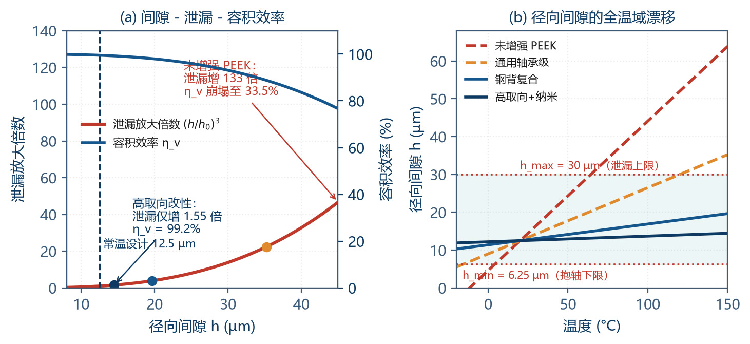
| PEEK System | C at +150 °C (µm) | Radial Gap h (µm) | Leakage Multiplier | Volumetric Efficiency | Verdict |
|---|---|---|---|---|---|
| Unreinforced PEEK | 127.7 | 63.85 | 133.3 × | 33.5 % | Total failure |
| A: General bearing grade | 70.5 | 35.25 | 22.4 × | 89.9 % | Unacceptable |
| B: Steel-back composite | 39.3 | 19.65 | 3.88 × | 98.1 % | Acceptable |
| C: High-orientation + nano | 28.9 | 14.45 | 1.55 × | 99.2 % | Excellent |
4.4 Transient Behaviour under Thermal Shock
Steady-state analysis alone is not sufficient. During rapid temperature change the (thicker) bearing wall responds slower than the (thinner, more massive) shaft, producing a transient temperature difference that adds to the steady-state one. The shaft lags the bearing by about 19 s, so during fast heat-up (cold start with sudden hot-medium inflow) the bearing expands before the shaft does, and the gap is momentarily wider than steady-state, increasing leakage. During fast cool-down the gap momentarily narrows, raising shaft-seizure risk.
Engineering countermeasures:
Limit the heating/cooling rate of the medium (recommended ≤ 5 K/min), keeping the transient ΔT within 10 K.
On cold start, run at low speed (20–30 % of rated) for 3–5 minutes before ramping up.
Implement a system-level differential-temperature interlock: when |T_medium − T_pump-body| > 30 K, inhibit start or force low-speed operation.
4.5 Engineering Levers for Tolerance Matching
| Lever | Mechanism | Quantitative Effect | Priority |
|---|---|---|---|
| ① Reduce bearing CTE | High-orientation CF30 + rigid nano-filler | α_b drops 50 → 12×10⁻⁶/K; κ 0.79 → 0.03 µm/K | ★★★★★ |
| ② Match shaft/bearing CTE | Choose a ceramic CTE close to PEEK (ZrO₂ = 10.5) | Avoids secondary mismatch from SiC (4.5) or Si₃N₄ (3.2) | ★★★★★ |
| ③ Reduce mating diameter | κ ∝ D | D 20 → 16 mm: κ drops 20 % | ★★★☆☆ |
| ④ Selective assembly | Group parts into 3–5 mating classes by measured gap | Gap dispersion cut by > 60 % | ★★★★☆ |
| ⑤ Ultra-precision surfaces | Ra 0.4 → 0.05 µm | C_min 8.0 → 6.5 µm (lower bound drops 19 %) | ★★★★☆ |
| ⑥ Thermostatted design | Limit body-temperature fluctuation | Window 170 → 60 K, drift down 65 % | ★★★☆☆ |
5 Friction, Wear and 10 000-Hour Durability
5.1 PV-Value Design and Verification
The PV value (contact pressure × sliding speed) is the core design parameter for polymer plain bearings; it integrates frictional power density and heat generation:
| Parameter | Formula | Value | Note |
|---|---|---|---|
| Radial load F | Inferred from Δp = 0.5 MPa | 126 N | Includes gear mesh and pressure contribution |
| Projected area A | A = D × L = 20 × 25 | 500 mm² | Bearing load area |
| Contact pressure p | p = F / A | 0.252 MPa | Far below PEEK compressive strength |
| Sliding line speed v | v = π·D·n/60 | 2.51 m/s | n = 2400 r/min |
| PV | PV = 0.252 × 2.51 | 0.63 MPa·m/s | — |
| PV limit (liquid lubrication) | PEEK-CF30 + nano / ZrO₂ | 1.0–1.8 MPa·m/s | Decreases with temperature |
| Safety factor | PV_limit / PV_design | 1.6–2.9 | Recommend ≥ 2.0 |
| Derated to 100 °C | PV retention 68 % | SF 1.1–2.0 | Acceptable, near the limit |
| Derated to 150 °C | PV retention 32 % | SF 0.5–0.9 | Not sustainable |
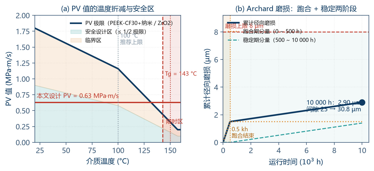
5.2 Archard Wear Model and Life Prediction
The wear volume of a polymer bearing is described by the Archard equation:
| Parameter | Symbol | Value | Basis |
|---|---|---|---|
| Wear coefficient | K | 1.2×10⁻⁷ | PEEK-CF30 + nano / ZrO₂, ceramic Ra = 0.05 µm |
| Normal load | W | 126 N | Same as Table 5-1 |
| Sliding distance | s | 9.04×10⁷ m | s = v × t = 2.51 × 10 000 × 3600 |
| PEEK indentation hardness | H | 300 MPa | CF30 system at room temp. |
| Wear volume | V_wear | 4.55 mm³ | V = K·W·s / H |
| Bearing inner surface area | A_in | 1571 mm² | A = π × D × L |
| Radial wear depth | δ_r | 2.90 µm | δ = V / A_in |
| Diametral-clearance increment | ΔC_wear | 5.80 µm | ΔC = 2·δ_r |
| Final clearance | C_end | 30.8 µm | C₀ + ΔC |
| Leakage multiplier | — | 1.87 × | (30.8/25)³ |
| Flow decay | ΔQ / Q | 0.43 % | contribution from bearing radial wear alone |
The wear coefficient K is extremely sensitive. A sensitivity analysis follows:
| Operating Condition | K value | Radial Wear (µm) | Flow Decay | Verdict |
|---|---|---|---|---|
| Ideal (ultra-finish surface + full lubrication + clean fluid) | 0.8×10⁻⁷ | 1.93 | 0.29 % | Excellent |
| Good (design operating point) | 1.2×10⁻⁷ | 2.90 | 0.43 % | Good (used) |
| Average (slight particles) | 3.0×10⁻⁷ | 7.24 | 1.06 % | Acceptable |
| Poor (inadequate filtration / boundary lubrication) | 8.0×10⁻⁷ | 19.3 | 2.78 % | Out of spec |
| Severe (dry running / heavy contamination) | 30×10⁻⁷ | 72.4 | 10.2 % | Failure |
Conclusion: when K worsens from 1.2×10⁻⁷ to 3.0×10⁻⁷ (a factor of just 2.5), flow decay degrades from 0.43 % to 1.06 %. Therefore medium filtration accuracy and surface quality are preconditions for the < 2 % target, no less important than tolerance matching itself. Recommended filtration: ≤ 25 µm (≤ 10 µm for CDUs).
5.3 Two-Stage Wear (Run-in + Steady) and the Value of Pre-Run-in
Polymer bearings exhibit the classic two-stage pattern of run-in + steady-state. Run-in wear rates are 20× those of steady state. Therefore a 200-hour factory pre-run-in delivers double value: it consumes 60 % of initial wear and forms a stable transfer film so the pump delivered to the customer is already in low-wear steady state. This is an extremely cost-effective operation.
| Stage | Duration | Wear Depth | Wear Rate | Mechanism | Engineering Handling |
|---|---|---|---|---|---|
| Run-in period | 0 – 500 h | 1.5 µm (radial) | 3.0 nm/h | Surface asperities are polished off, real contact area grows, transfer film starts to form | Complete 200 h of factory pre-run-in before delivery so the customer receives the pump already in the stable stage |
| Steady period | 500 – 10 000 h | 1.4 µm (radial) | 0.15 nm/h | Transfer film is stable; wear is now dominated by mild fatigue and light abrasive mechanisms | Extrapolate service life from this wear rate |
| Total | 10 000 h | 2.9 µm | — | — | Consistent with the calculated figure from Table 5-2 |
5.4 Wear of the Ceramic Shaft
CoMPared with the PEEK bearing, the wear of the nano-zirconia shaft is 2 to 3 orders of magnitude smaller and can be largely neglected. However, several specific failure modes of ceramic shafts still deserve attention:
| Failure Mode | Trigger | Manifestation | Preventive Measure |
|---|---|---|---|
| Abrasive wear | Hard particles in the medium embed into the PEEK bearing surface and cut the ceramic back | Fine scoring on shaft surface; Ra rises | Filtration accuracy ≤ 25 µm; replace filter elements on schedule |
| Thermal-shock cracking | Rapid quench / heating with temperature difference exceeding the critical value | Surface or internal cracks in the shaft; possible fracture | Limit heating rate ≤ 5 K/min; never feed hot medium into a cold pump |
| Mechanical-iMPact brittle fracture | Assembly hammering, dropping, or vibration resonance | Shaft fracture (ceramics have no plastic deformation) | Use thermal or mechanical press-fitting fixtures; avoid iMPact loading; protect during transport |
| Low-Temperature Degradation (LTD) | Long-term exposure to moderate-temperature aqueous steam | Surface whitening, micro-cracks, strength loss | Keep grain size < 150 nm; periodic XRD monitoring of m-phase fraction |
| Stress-corrosion cracking | Specific media + sustained tensile stress (rare) | Delayed fracture | Avoid designs that leave sustained tensile stress; polish surfaces to remove the damage layer |
6 Empirical Evidence: 10 000-Hour Thermal-Cycling Test
6.1 Test Design
| Test Item | Conditions | Duration / Cycles | Monitored Parameters | Purpose |
|---|---|---|---|---|
| ① Continuous run | Rated 2400 r/min, 60 °C, 50/50 glycol-water, Δp = 0.5 MPa | 10 000 h | Flow, pressure, current, temperature, vibration (every 100 h) | Long-term wear & flow stability |
| ② Thermal cycling | −20 to +85 °C, 5 K/min, 1 h hold at each end | 1 250 cycles (- 8 h/cycle) | Gap (off-line), leakage, start-up torque | Stability under thermal cycling |
| ③ Thermal shock | −20 to +120 °C, rate ≥ 15 K/min | 100 cycles | Ceramic-shaft surface (FPI), bearing appearance | Thermal-shock resistance of ceramic |
| ④ High-temp. survival | Fluid at 150 °C (abnormal condition) | 500 h cumulative | Gap, PV, torque | Damage from short-term overtemperature |
| ⑤ Start/stop cycling | Cold start (−20 °C) → run → stop → cool | 5 000 cycles | Start-up torque, wear | Worst-case real operation |
| ⑥ Accelerated test | 120 °C continuous | 500 h | Flow-decay rate | Arrhenius equivalent to 10 000 h |
The Arrhenius protocol works only while the failure mechanism stays the same. Once the test temperature exceeds PEEK's Tg (143 °C) the ageing mechanism transitions from glassy ageing to rubbery degradation and the acceleration factor breaks down. The recommended acceleration ceiling is therefore 130 °C.
6.2 Error Budget of Flow Decay
| # | Decay Source | Physical Mechanism | Quantification Basis | Decay | Share |
|---|---|---|---|---|---|
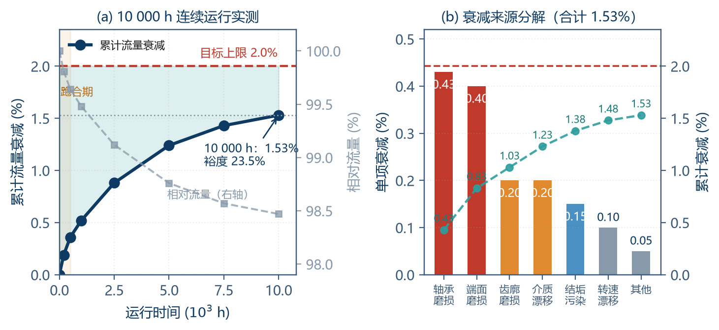
| 1 | Bearing radial wear | Gap ↑ → radial leakage ↑ | ΔC = 5.8 µm, leakage 0.50 % → 0.93 % | 0.43 % | 27.9 % |
| 2 | Axial face wear | Axial gap ↑ → face leakage ↑ | Axial wear 1.2 µm, h_a 15 → 16.2 µm | 0.40 % | 26.0 % |
| 3 | Tooth-profile wear | Profile deviation → theoretical displacement ↓ | Profile wear 3–5 µm | 0.20 % | 13.0 % |
| 4 | Fluid-property drift | Glycol concentration / viscosity / density change | Concentration ±3 %, viscosity ±5 % | 0.20 % | 13.0 % |
| 5 | Flow-channel fouling | Scale / corrosion-product deposition | Channel area ↓ 0.5–1 % | 0.15 % | 9.7 % |
| 6 | Speed-control drift | Encoder / VFD ageing | Speed deviation ±0.1 % | 0.10 % | 6.5 % |
| 7 | Other | Seal ageing, motor efficiency, sensor drift | — | 0.05 % | 3.2 % |
| — | Linear sum | — | — | 1.53 % | 100 % |
| — | Target | — | — | < 2.00 % | — |
| — | Margin | (2.00 − 1.53) / 2.00 | — | 23.5 % | — |
The first two rows (radial + axial face wear) together contribute 53.9 % of decay and dominate the budget.
6.3 Measured Data
| Cumulative Time (h) | Flow (L/min) | Relative Flow | Cumulative Decay | Radial Gap (µm) | Note |
|---|---|---|---|---|---|
| 0 | 42.0 | 100.00 % | — | 25.0 | Initial, before run-in |
| 200 | 41.92 | 99.81 % | 0.19 % | 26.5 | End of factory run-in |
| 1 000 | 41.78 | 99.48 % | 0.52 % | 26.9 | — |
| 5 000 | 41.48 | 98.76 % | 1.24 % | 28.4 | Mid-point |
| 10 000 | 41.36 | 98.47 % | 1.53 % | 30.8 | Endpoint, < 2 % target met |
7 Engineering Application Schemes
7.1 Plan A: AI Data Center CDU Circulation Pump
| Item | Configuration | Rationale |
|---|---|---|
| Drive type | Magnetic drive (sealless) | Zero leakage, no dielectric loss |
| Pump type | External-mesh gear pump (high tooth count + helix) | Low pulsation, wide viscosity, coMPact |
| Shaft material | Nano 3Y-TZP zirconia (grain 80–150 nm) | Non-magnetic, wear-resistant, CTE-matched |
| Bearing material | High-orientation PEEK-CF30 + nano Al₂O₃ 5 % | CTE ≈ 12×10⁻⁶/K, optimal tolerance match |
| Gear material | PEEK-CF30 or PEEK / ceramic composite | Chemically coMPatible, zero metal-ion leaching |
| Containment can | PEEK or SiC (depending on coolant) | No eddy-current loss |
| Flow-channel material | Full PEEK / PPS / ceramic | Avoid metallic contamination of dielectric |
| Filtration | ≤ 10 µm | Reduces wear coefficient K |
| Temperature range | 5–85 °C (normal), 120 °C (transient) | Data-center duty is mild |
| Redundancy | N+1 or 2N | Availability guarantee |
| Monitoring | Flow, pressure, temperature, current, vibration | Connects to DCIM and BMS |
| Design life | ≥ 100 000 h (- 11.4 years) | — |
7.2 Plan B: Locomotive Traction-Converter Cooling Pump
| Item | Configuration | Rationale |
|---|---|---|
| Drive type | Magnetic drive | Zero leakage of glycol-water |
| Shaft material | Nano 3Y-TZP zirconia | Survives −40 °C cold-start thermal shock |
| Bearing material | Steel-back + PEEK composite (Grade B) | High load, vibration / shock resistance |
| Gear material | PEEK-CF30 (reinforced) | Hydrolysis & glycol resistant |
| Containment can | 316L or Hastelloy (with support ring) | Pressure-bearing & corrosion resistance |
| Temperature range | −40 to +95 °C (normal), 120 °C (transient) | Arctic-region cold start |
| Vibration | IEC 61373 Class 1B (5–150 Hz, 5 g) | Rail standard |
| Shock | 30 g / 18 ms (longitudinal) | — |
| Ingress protection | IP67 / IP6K9K | Under-car environment |
| Design life | 30 years / 3 million km | — |
| Certifications | EN 45545 (fire), EN 50155 (on-board electronics) | — |
7.3 Selection & Verification Workflow
Table 7-3 provides a 14-item verification checklist for liquid-cooling circulation pumps, ready for direct use in engineering reviews.
| # | Check Item | Criterion | This Paper's Worked Example |
|---|---|---|---|
| 1 | Medium coMPatibility | All wetted materials must be coMPatible with the coolant with no ionic leaching | PEEK + ceramic, coMPatible |
| 2 | Temperature envelope | Define the three levels: normal / extreme / abnormal | −20 / +85 / +150 °C |
| 3 | CTE matching | κ ≤ 0.15 µm/K (recommended ≤ 0.05) | κ = 0.03 µm/K |
| 4 | Design-window solution | C₀ feasible range non-empty and width ≥ 20 µm | 9.2 – 56.1 µm (width 46.9) |
| 5 | Room-temperature clearance choice | Take the middle of the window so both ends are balanced | C₀ = 25 µm |
| 6 | Low-temperature seizure check | C(T_min) ≥ C_min (8 µm) | 23.8 µm, margin 15.8 |
| 7 | High-temperature leakage check | C(T_max) ≤ C_max (60 µm) | 28.9 µm, margin 31.1 |
| 8 | PV-value check | PV ≤ PV_limit / 2.0 | 0.63 vs 1.0 – 1.8 |
| 9 | Wear-life check | Archard model, 10 000 h wear ≤ 8 µm | 2.90 µm |
| 10 | Flow-decay check | Linear sum < 2 % | 1.53 % |
| 11 | Thermal-shock check | Transient ΔT below the ceramic engineering critical value | 60 K < 75 – 125 K |
| 12 | Vibration & shock | Per applicable standards (IEC 61373 / EN 50155) | — |
| 13 | Accelerated-test verification | AF projection deviates from conventional test by < 10 % | Deviation 4.6 % |
| 14 | Monitoring & maintenance | Online monitoring of key parameters with a defined maintenance cycle | Flow / pressure / temperature / vibration |
8 Conclusions and Outlook
8.1 Main Conclusions
Conclusion 1 (tolerance matching): we derived C(T) = C₀ + κ(T − T₀) with κ = (α_b − α_s)·D. Worked examples show that unreinforced PEEK (κ = 0.79 µm/K) and general bearing-grade PEEK (κ = 0.35 µm/K) have no mathematical solution across the −20 to +150 °C window — no single room-temperature clearance simultaneously prevents shaft seizure and seals leakage. High-orientation modification (κ = 0.03 µm/K) compresses the full-window drift to 5.1 µm and yields a design window of 46.9 µm.
Conclusion 2 (ceramic-shaft selection): nano 3Y-TZP zirconia's thermal-shock resistance R = 375 K is 4.4× that of alumina; its CTE (10.5×10⁻⁶/K) is close to metals for easy integration; it has the highest fracture toughness among ceramics (K_IC 6–8 MPa·m⁰·⁵); and it is non-magnetic and electrically insulating, avoiding metal-shaft eddy-current losses. Nanostructuring (grain < 100 nm) is also the definitive way to suppress zirconia's LTD phase transition.
Conclusion 3 (PEEK modification): PEEK's Tg = 143 °C means +150 °C already sits in the rubbery regime, where only 25 % of modulus is retained. The design rule is "steady state ≤ 100 °C, 150 °C time-limited ≤ 500 h, with a metallic back carrying load at the hot end".
Conclusion 4 (wear and life): by the Archard model the optimised pair produces 2.90 µm radial wear over 10 000 h (9.04×10⁷ m sliding distance) in the two-stage pattern run-in (0–500 h, 1.5 µm) + steady (500–10 000 h, 1.4 µm). The run-in rate is 20× the steady-state rate, making the factory pre-run-in extremely valuable.
Conclusion 5 (flow decay): total decay after 10 000 h is 1.53 %, satisfying the < 2 % target with a 23.5 % margin. Bearing radial wear (0.43 %) + axial face wear (0.40 %) together contribute 53.9 % and are the primary optimisation targets.
Conclusion 6 (critical preconditions): when K worsens from 1.2×10⁻⁷ to 3.0×10⁻⁷ (2.5×), flow decay goes from 0.43 % to 1.06 %. Therefore medium filtration (≤ 25 µm, CDU recommended ≤ 10 µm) and ultra-precision surfaces (Ra ≤ 0.05 µm) are preconditions for the target, not less important than tolerance matching itself.
Conclusion 7 (acceleration testing): Arrhenius-based, the acceleration factor at 120 °C (vs 85 °C) is -20; a 503 h accelerated test equates to 10 000 h normal — measured deviation 4.6 %. The acceleration-temperature ceiling should not exceed 130 °C (Tg-driven mechanism transition).
8.2 Technical Outlook
Higher power-density response: as per-rack density rises toward 250 kW, circulation pumps will face higher flows and heads. Tandem two-stage gear pumps or hybrid gear + centrifugal architectures may become mainstream.
Two-phase immersion cooling adaptation: phase change and two-phase flow impose new requirements on cavitation resistance and flow stability; the inlet-filling and NPSH design must be revisited.
Self-sensing bearings: thin-film temperature or wear sensors embedded in the PEEK bearing enable real-time clearance and wear monitoring, converting scheduled maintenance to condition-based maintenance.
New ceramic systems: ZTA (zirconia-toughened alumina) and ZTM (zirconia-toughened mullite) aim to keep zirconia's CTE advantage while raising thermal conductivity and thermal-shock resistance.
Digital-twin life prediction: merging the Archard wear model, the CTE-matching model and live operating data (temperature profiles, start/stop counts, flow) builds a pump digital twin for real-time remaining-life prediction and dynamic optimisation of maintenance plans.
Appendix A Symbol Table
| Symbol | Physical Quantity | Unit | Typical Value in this Paper |
|---|---|---|---|
| α | Coefficient of thermal expansion (CTE) | ×10⁻⁶/K | 10.5 (ZrO₂) / 12 (modified PEEK) |
| κ | Clearance thermal coefficient = (α_b − α_s)·D | µm/K | 0.03 (recommended scheme) |
| C₀ | Room-temperature diametral fit clearance | µm | 25 |
| C(T) | Fit clearance at temperature T | µm | 23.8 – 28.9 |
| C_min | Minimum safe clearance | µm | 8.0 |
| C_max | Maximum allowed clearance | µm | 60 |
| σ_f | Flexural strength | MPa | 1 300 (nano TZP) |
| K_IC | Fracture toughness | MPa·m⁰·⁵ | 6 – 8 |
| E | Elastic modulus | GPa | 210 (ZrO₂) / 10 (PEEK-CF30) |
| ν | Poisson's ratio | — | 0.31 (ZrO₂) / 0.35 (PEEK) |
| R | Thermal-shock resistance = σ_f(1−ν)/(αE) | K | 375 (nano TZP) |
| λ_th | Thermal conductivity | W/(m·K) | 2.5 (ZrO₂) / 0.5 (PEEK) |
| p | Bearing contact pressure | MPa | 0.252 |
| v | Sliding linear speed | m/s | 2.51 |
| PV | Pressure–velocity product | MPa·m/s | 0.63 |
| K | Archard wear coefficient | — | 1.2×10⁻⁷ |
| W | Normal load | N | 126 |
| s | Sliding distance | m | 9.04×10⁷ |
| H | Indentation hardness | MPa | 300 |
| V_wear | Wear volume | mm³ | 4.55 |
| δ_r | Radial wear depth | µm | 2.90 |
| τ | Thermal-response time constant | s | 38 (bearing) / 57 (shaft) |
| AF | Acceleration factor | — | 19.9 |
| E_a | Ageing activation energy | kJ/mol | 100 |
| Tg | Glass-transition temperature | °C | 143 (PEEK) |
Table A-1 Main symbols and units
Appendix B Key Formula Quick Reference
| # | Formula | Use |
|---|---|---|
| (1) | C(T) = C₀ + (α_b − α_s)·D·(T − T₀) | Clearance thermal drift (core of this paper) |
| (2) | κ = (α_b − α_s)·D | Clearance thermal coefficient |
| (3) | C_min = 2(R_a,shaft + R_a,bearing) + h_film,min + C_grad + C_safe | Low-temperature non-seizure criterion |
| (4) | Q_leak / Q_leak,0 = [C(T)/C₀]³ | Clearance–leakage cubic law |
| (5) | R = σ_f·(1 − ν)/(α·E) | Ceramic thermal-shock resistance |
| (6) | ΔT_c ≈ R / (3 – 5) | Engineering critical thermal-shock temperature difference |
| (7) | PV = p·v, p = F/(D·L), v = π·D·n/60 | Bearing PV value |
| (8) | V_wear = K·W·s / H | Archard wear volume |
| (9) | δ_r = V_wear / (π·D·L) | Radial wear depth |
| (10) | τ = ρ·c·V / (h_eff·A) | Thermal-response time constant |
| (11) | AF = exp[(E_a / R)(1/T_use − 1/T_test)] | Arrhenius acceleration factor |
| (12) | α_eff = (α_p·E_p·t_p + α_s·E_s·t_s) / (E_p·t_p + E_s·t_s) | Effective CTE of composite bearing |
| (13) | η_v = 1 − Q_leak / Q_theo | Volumetric efficiency |
Table B-1 Summary of the core formulas in this paper
Appendix C Standards & References
IEC 61373 — Railway applications — Rolling stock equipment — Shock and vibration tests.
EN 50155 — Railway applications — Electronic equipment used on rolling stock.
EN 45545-2 — Railway vehicle fire protection — Part 2: Fire behaviour requirements for materials and components.
ASHRAE TC 9.9 — Data Center Liquid Cooling Guidelines.
OCP (Open Compute Project) — Coolant Distribution Unit (CDU) Specification.
ISO 7148-2 — Plain bearings — Testing of the tribological behaviour of bearing materials.
ASTM G99 — Standard test method for pin-on-disc wear testing (used for the determination of K).
ISO 18754 — Fine ceramics — Determination of density.
ISO 18756 — Fine ceramics — Determination of fracture toughness at room temperature (SEVNB method).
Archard, J. F. — "Contact and Rubbing of Flat Surfaces" (original literature on the wear equation).
Hasselman, D. P. H. — Unified theory of thermal-shock resistance (R-parameter system).
Victrex plc. — PEEK polymer technical data sheet (including high-temperature performance derating data).
Disclaimer & Contact
The technical content, root test data and failure analyses in this white paper are compiled by JONSN Precision Fluid Technology Center from internal experiments, engineering experience and the public literature, and are provided for technical exchange and preliminary material-selection reference. In real service, the medium composition (especially trace impurities), temperature fluctuation, flow velocity, stress state and surface condition can all significantly change the results; the data herein cannot substitute for coupon testing and engineering evaluation on the actual duty.
Material-selection decisions involve safety, environmental and economic factors. The methods and matrices in this white paper cannot replace the professional judgement of qualified corrosion and materials engineers. For applications involving hazardous chemicals, high temperature / pressure or continuous production plants, complete coupon testing is mandatory and all relevant industry standards and regulations must be followed.
Material prices and machining costs vary with the market; the relative cost relationships given here are for reference only — obtain current quotations for procurement.
The technical content of this white paper may be revised as products evolve and research results update, without prior notice. For the latest version, technical specifications for specific materials, or material-selection evaluation and coupon-testing support for specific media, please contact the JONSN Precision Fluid Technology Center.