







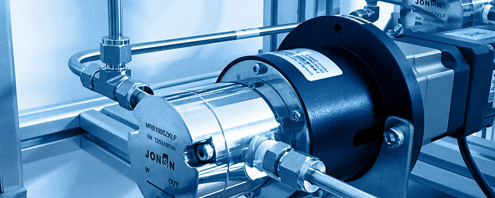
Volumetric Pulsation Suppression and Microliter Precision of Micro Gear Metering Pump
Abstract
Microfluidic metering is crossing a new precision boundary: dispense volumes step down from millilitre-class to microlitre-class (1 µL = 1 mm³); repeatability tightens from ±2 % to ±0.2 %; the absolute error target per dispense falls into the 100 nL class — equivalent to about one-thousandth of a 0.58 mm droplet. Drivers include semiconductor photoresist coating and CMP slurry delivery, in-vitro diagnostic (IVD) reagent dispensing, haemodialysis concentrate blending, lithium-battery electrode slurry coating, and large-format digital printing pigment / UV-ink dosing — where "every drop must be identical" is a hard requirement.
Among the micro-flow technology routes, the external-mesh gear pump — with its continuous no-valve delivery, extreme viscosity window (1 - 10⁵ MPa·s), coMPact volume and low-shear characteristics — has become one of the mainstream solutions for microliter metering. But it simultaneously bears three inherent physical bottlenecks: (1) geometric-level volume-flow pulsation and oil trapping, rooted in the kinematic discontinuity of gear meshing; (2) material-mechanics-level: the PEEK (poly-ether-ether-ketone) tooth face, widely used for chemical coMPatibility and self-lubrication, has an elastic modulus of only -1/50 of alloy steel, producing micrometer-level deformation under back-pressure and back-pressure-sensitive displacement drift; (3) fluid-level: three-gap leakage, incomplete inlet filling and non-Newtonian medium effects non-linearly couple volumetric efficiency with pressure, viscosity, speed and temperature.
This white paper systematically deconstructs the generation and elimination mechanisms of flow pulsation in micro gear metering pumps — from three perspectives: meshing geometry, contact mechanics and fluid dynamics — and presents a quantifiable engineering path to ±0.2 % repeatability:
1Geometry layer: from the closed-form instantaneous-flow equation we derive the pulsation ratio δ = (π²cos²α/4) / [(z·h*_a + h*_a²) − π²cos²α/12], quantifying how tooth count z, pressure angle α and addendum coefficient h*_a weigh into pulsation; explains the dual role of contact ratio ε_α between "ensuring continuous meshing" and "inducing oil trapping", gives relief-groove design rules, and quantifies how axial contact ratio ε_β (helix angle) suppresses pulsation — at ε_β ≥ 1.0 relative pulsation drops below 6 % of the spur-gear baseline.
2Material-mechanics layer: builds the full load chain from outlet back-pressure to flank normal force, and obtains via Hertz line-contact model and cantilever-bending model the PEEK-flank elastic approach (-0.3 – 0.6 µm, sub-micron class) and tooth-body bending (-3 – 6 µm, micrometre class), pointing out that the latter is the dominant contributor to back-pressure-sensitive displacement drift dq/dp; simultaneously demonstrates the positive value of micro-elasticity in absorbing pitch errors, achieving near-zero-backlash soft meshing, and low-pass-filtering pulsation, proposes a three-pronged strategy of "deformation-compensating flank profile + pressure-balanced flow path + hydraulically compensated side plate", and gives quantitative criteria for side-plate deflection — pure-PEEK side plate can deflect up to 24 µm at 1 MPa, far exceeding the face-clearance design value, so the face pair must use a high-modulus material or a hydraulically compensated structure.
3Fluid layer: builds the face / radial / mesh-line three-gap leakage model, revealing the cubic dependence of leakage on gap (h³ law) with both pressure-driven and shear-driven components; gives the inlet filling adequacy criterion and apparent-viscosity correction method for non-Newtonian media, pointing out that the leakage share explodes at very low speeds — the same pump at 600 r/min has -0.2 % leakage share but at 6 r/min it can exceed 20 %, which is the most underestimated error source in microliter low-flow applications.
4Precision-budget layer: builds an error budget allocation table for ±0.2 % repeatability, controlling each of 11 error sources within ±0.05 %, with RSS combination yielding ±0.095 % (k = 1), expanded uncertainty ±0.19 % (k = 2), satisfying the ±0.2 % target with about 5 % margin.
Finally, the paper uses the gravimetric method as the metrological reference, gives a full-matrix empirical scheme ("3 media × 4 pressures × 3 temperatures × 3 flow points"), statistical definitions & acceptance criteria, and a multi-dimensional coMParison of micro gear pumps with plunger, syringe, peristaltic and diaphragm pumps, plus application mapping to six target industries. All quantitative worked examples are based on a single publicly declared set of typical structural parameters (m = 0.3 mm, z = 14, B = 3 mm, α = 20°, h*_a = 1.0), used to illustrate the order of magnitude of mechanisms; specific products must be re-checked against their actual geometry.
1 Introduction — Precision Boundary of Microliter Metering & Inherent Contradictions of Gear Pumps
1.1 From Millilitres to Microlitres — Redefining Precision
In traditional industrial fluid transport, "metering accuracy" is loosely expressed as a percentage. When the dispense volume reaches the microlitre class, the percentage alone can no longer describe system capability — the indicator must be split into four independent, non-substitutable dimensions:
| Indicator | Definition | Physical Dominant Factor | Can Calibration Eliminate It? |
|---|---|---|---|
| Repeatability | Run-to-run consistency at fixed duty, RSD = s / x̄ | Drive resolution, mechanical backlash, instantaneous pulsation, medium degassing state | No, only improvable |
| Accuracy | Bias between mean dispense and set point, Bias = (x̄ − x_set)/x_set | Theoretical displacement deviation, leakage, medium compressibility | Largely eliminated by 1-point / multi-point calibration |
| Linearity | Envelope of accuracy across setpoints (10/50/100 % FS) | Volumetric-efficiency speed dependence, non-linear leakage | Compensated by segmented calibration |
| Pressure sensitivity S_p | Fractional flow change per unit back-pressure, %/MPa | Tooth-body elastic deformation, side-plate deflection, gap leakage | Partially compensated by feedforward |
Table 1-1 Four core precision indicators of micro-metering and their physical meanings
The biggest misconception in engineering practice is to treat "accuracy" as the only indicator. In processes like semiconductor coating and IVD dispensing, which repeat the same action many times in succession, repeatability (RSD) is the lifeline of yield and consistency — accuracy bias can be eliminated with a single calibration, but poor repeatability means every wafer and every reagent tube is randomly varying with no post-hoc remedy. This paper therefore defines ±0.2 % explicitly as the repeatability indicator (RSD, n ≥ 100) and decomposes the error budget backwards against this target.
1.2 Magnitude Intuition for Microlitres
| Dispense Volume | Equivalent Geometry (water) | Absolute Error for ±0.2 % | Typical Application |
|---|---|---|---|
| 1000 µL | ∅ 12.4 mm sphere | ±2000 nL | Standard lab pipetting |
| 100 µL | ∅ 5.76 mm sphere | ±200 nL | IVD reagent dispensing, dialysis concentrate blending |
| 10 µL | ∅ 2.67 mm sphere | ±20 nL | Photoresist top-up, jetting |
| 1 µL | ∅ 1.24 mm sphere | ±2 nL | Inkjet head feed, microarray spotting |
Table 1-2 Magnitude reference for microlitre volumes
Note: sphere equivalent diameter is calculated as V = πd³/6, used to build a spatial intuition of the volume magnitude; actual dispense is a continuous liquid stream or column, not a spherical droplet.
For coMParison: a single drop from a standard pipette is -20 – 50 µL, with typical drop-to-drop variation 1 – 3 %. In other words, ±0.2 % repeatability compresses the dispersion of "drop" events by more than an order of magnitude, and must be maintained continuously under industrial conditions of pressurised, wide-temperature, variable-viscosity flow — exactly the technical barrier facing micro gear metering pumps.
1.3 Why Gear Pumps — Strengths and Inherent Contradictions
The competitiveness of external-mesh gear pumps in the microlitre window stems from their "continuous positive-displacement" principle: each gear rotation transports a defined tooth-space volume from inlet to outlet, in theory strictly proportional to speed, without check valves, reversing dead zones or compressible chambers. Four direct advantages follow:
Continuous, pulse-free reversal: coMPared with the flow drop and pressure shock at reversal in syringe / piston pumps, the gear-pump output is continuous in time, naturally suitable for coating and spraying processes sensitive to instantaneous flow.
Extremely wide viscosity window: covers 1 to 100 000 MPa·s, from low-viscosity solvents to high-viscosity photoresist and slurries, while peristaltic pumps suffer severely under high viscosity due to insufficient tube recoil.
Low and short shear history: for media containing long-chain polymers, pigment particles or biologically active ingredients, the gear pump's single-pass shear is much lower than high-speed dispersion or piston throttling, protecting medium performance.
CoMPact, low dead volume: micro-module gear pumps can fit in a palm-sized envelope with internal dead volume of only tens of microlitres, reducing medium-loss during change-over — important for expensive photoresist and biological reagents.
But the inherent contradictions are equally sharp. First, the instantaneous flow is intrinsically non-uniform — this is a kinematic inevitability, only suppressible, not eliminable. Second, to guarantee continuous meshing the contact ratio must be > 1, but ε_α > 1 necessarily leads to oil trapping — at the moment when two tooth pairs mesh simultaneously, a closed trapped volume is formed whose volume first shrinks then expands with rotation, and pressure can surge to several times the discharge pressure in the compression phase. Third, the absolute size of micro-pump parts is very small (module 0.2 – 0.5 mm, face width 2 – 5 mm), where material elasticity is no longer a negligible second-order small quantity: the bending deformation of a PEEK tooth under 1 MPa back-pressure can reach 0.8 % of tooth height, entering the same order of magnitude as the profile error itself.
These three contradictions form the paper's argument line: Chapter 2 addresses the first (geometric pulsation), Chapter 3 addresses the third (elastic deformation), Chapter 4 addresses the second and the fluid coupling, Chapter 5 turns the three into an executable error budget & engineering path, Chapter 6 gives the verification methodology.
2 Geometric Origin — Contact-Ratio Coefficient & Pulsation Mechanism of Instantaneous Flow
2.1 Closed-Form Expression for Instantaneous Flow
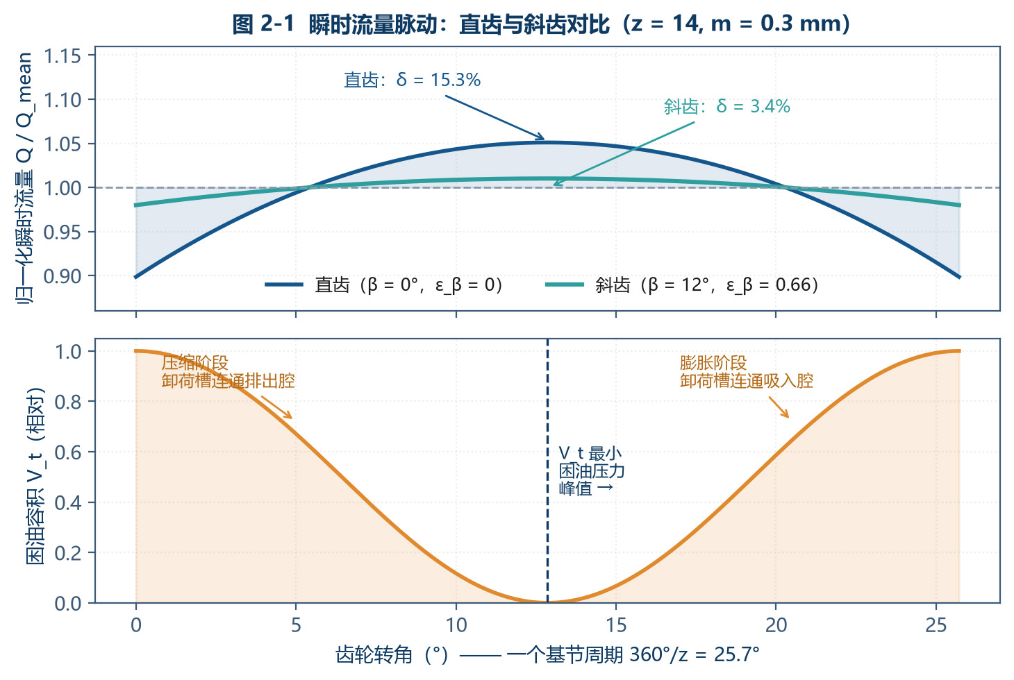
The instantaneous flow of an external-mesh gear pump can be derived directly from the "swept volume rate" of the gear pair. With two gears of equal tooth count (z₁ = z₂ = z), module m, face width B, pressure angle α, addendum coefficient h*_a, angular velocity ω. Let f be the signed distance along the line of action from the pitch point P to the mesh point K. Then the instantaneous flow is:
where r = mz/2 is the pitch radius and r_a = r + h*_a·m is the tip radius. This reveals a critical fact: the instantaneous-flow fluctuation comes entirely from the f² term. f varies periodically within [−p_b/2, +p_b/2] (where p_b = π·m·cosα is the base pitch) as the gears rotate, with a period of 1/z revolution. Therefore:
When f = 0 (mesh point at pitch point), Q_max = B·ω·(r_a² − r²);
When |f| = p_b/2 (mesh point at the base-pitch endpoint), Q_min = B·ω·[(r_a² − r²) − (p_b/2)²];
Pulsation frequency is f_Q = z·n/60 (Hz) — z pulses per revolution, the source of gear-pump characteristic noise.
Integrating f² over one base-pitch interval and taking the mean gives the average flow and the closed-form pulsation ratio:
Substituting geometric quantities and normalising (m² as common factor), we obtain the engineering form:
Applicability: standard spur external-mesh, equal tooth count, standard mounting (no modification), addendum coefficient h*_a, constant face width. Modified gears must be re-checked with actual r_a and operating pressure angle α′.
2.2 Quantitative Influence of Tooth Count, Pressure Angle and Addendum
The expression above decomposes pulsation into the ratio of "fluctuation source" (numerator — pressure-angle-dependent) to "carrying base" (denominator — tooth count and addendum-dependent). Three direct design directions: larger tooth count, larger addendum, larger pressure angle all reduce pulsation. Table 2-1 shows the variation with tooth count at α = 20°, h*_a = 1.0:
| Tooth Count z | Pitch Diameter (mm, m = 0.3) | Contact Ratio ε_α | Flow Pulsation δ | Relative to z = 9 |
|---|---|---|---|---|
| 9 | 2.7 | 1.34 | 23.5 % | 100 % |
| 10 | 3.0 | 1.37 | 21.2 % | 90 % |
| 12 | 3.6 | 1.42 | 17.7 % | 75 % |
| 14 | 4.2 | 1.47 | 15.3 % | 65 % |
| 16 | 4.8 | 1.50 | 13.4 % | 57 % |
| 18 | 5.4 | 1.53 | 11.9 % | 51 % |
| 20 | 6.0 | 1.56 | 10.7 % | 45 % |
| 24 | 7.2 | 1.61 | 9.0 % | 38 % |
| 28 | 8.4 | 1.61 | 7.7 % | 33 % |
Table 2-1 Effect of tooth count on pulsation and contact ratio (α = 20°, h*_a = 1.0)
Influence of pressure angle and addendum coefficient can also be quantified. Table 2-2 takes z = 14 as baseline and scans both parameters:
| Parameter Combination | Contact Ratio ε_α | Pulsation δ | Evaluation |
|---|---|---|---|
| α = 14.5°, h*_a = 1.0 | 1.65 | 16.2 % | Highest contact ratio, good tooth-root strength; but large pulsation & high bearing radial force |
| α = 20.0°, h*_a = 1.0 | 1.47 | 15.3 % | Standard scheme; balanced (reference) |
| α = 25.0°, h*_a = 1.0 | 1.35 | 14.1 % | Pulsation drops 8 %, but contact ratio drops, tip thinness risk |
| α = 28.0°, h*_a = 1.0 | 1.29 | 13.4 % | Lowest pulsation, contact ratio near 1.0, oil-trapping control harder |
| α = 20.0°, h*_a = 0.8 | 1.31 | 19.6 % | Short-tooth scheme; pulsation significantly worse, not recommended |
| α = 20.0°, h*_a = 1.1 | 1.55 | 13.7 % | High-tooth scheme; pulsation improves markedly |
| α = 20.0°, h*_a = 1.2 | 1.63 | 12.4 % | High-tooth scheme; pulsation further lower; tip thickness to be verified |
| α = 20.0°, h*_a = 1.25 | 1.67 | 11.9 % | Near tip-thinning limit; tip-relief required |
Table 2-2 Effect of pressure angle α and addendum coefficient h*_a on pulsation (z = 14)
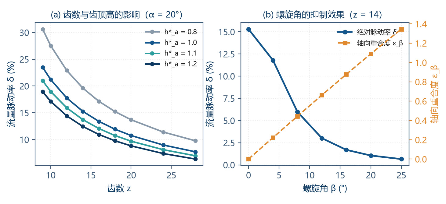
From Table 2-2 a frequently overlooked rule emerges: addendum coefficient influences pulsation more than pressure angle. Raising h*_a from 1.0 to 1.2 cuts pulsation by -19 %; raising α from 20° to 28° only cuts it by -12 %, at the cost of dropping contact ratio from 1.47 to 1.29. Therefore in micro-pump design, prefer "standard pressure angle + moderately high addendum + tip relief" rather than blindly enlarging the pressure angle.
2.3 Dual Role of Contact Ratio ε_α
The transverse contact ratio is defined as the ratio of actual contact-line length to the base pitch:
The contact ratio plays two conflicting roles in a gear pump:
Positive: ε_α > 1 is required to guarantee continuous transmission and avoid mesh interruption. If ε_α < 1, at some angles no tooth pair will be in contact, suction and discharge chambers connect directly, and the pump loses the basic premise of positive-displacement work. Engineering requires ε_α ≥ 1.2, recommended 1.4 – 1.7.
Negative: ε_α > 1 means there are instants when two tooth pairs are simultaneously in mesh; the two mesh points and the tooth profiles enclose a closed "oil trapped volume" V_t. This volume first shrinks then expands with rotation; in the shrinking phase the trapped liquid cannot escape through any channel and pressure rises sharply (measured 2 – 4× discharge pressure); in the expanding phase a local vacuum forms, inducing cavitation and noise.
Three precision-degrading effects of oil trapping must be made explicit:
Radial-force spikes: the trapped-oil pressure acts on the flank, producing cyclic radial-force spikes that propagate via bearings to micro-displace the rotor axis, breaking face-gap uniformity and creating cyclic leakage pulses.
Leakage-channel distortion: the trapped pressure locally forces the flank and side plate to retreat elastically, momentarily opening the gap and creating a leakage pulse synchronised with the trapped-volume cycle — leakage beyond the steady-state model, the source of "pulsation-correlated leakage".
Medium damage: for photoresist, biological reagents and pigment dispersions, the high pressure and high shear in the trapped zone cause local degradation, particle breakage or agglomeration.
2.4 Eliminating Oil Trapping — Relief-Groove Design Rules
The standard engineering remedy is to cut relief grooves in the side plate (or end cover) so that the trapped volume is always connected to the correct chamber throughout its volume cycle: connected to the discharge (high-pressure) side during the compression phase, and to the inlet (low-pressure) side during expansion; at the extreme of the trapped volume it is momentarily connected to neither side.
| Design Element | Design Rule | Typical Value for Micro Pump | Deviation Consequence |
|---|---|---|---|
| Groove spacing a_g | Inner-edge distance = axial projection between two mesh points at trapped-volume minimum | Calculated from ε_α and centre distance; tolerance ±0.02 mm | Too large → high/low pressure interconnection, ηᵥ drop; too small → oil trap not eliminated |
| Groove depth | Flow area enough to discharge trapped-volume change within compression time | 0.3 – 0.8 mm | Too shallow → incomplete relief; too deep → face-end seal area loss |
| Groove shape | Rectangular or gradually expanding; edge rounded R0.1 to avoid stress concentration | Rectangular with fillet | Sharp corner → trapped-oil residual & cleaning dead-leg |
| Symmetry | Suction / discharge sides & front/rear end covers symmetric | Double-side symmetry | Single-side → axial eccentric load, single-side face gap increase |
| Phase alignment | Groove centre-line offset vs gear centre-line must match mesh phase | Dowel-pin positioning, repeatability ±0.02 mm | Phase deviation → relief-window misalignment, effectiveness lost |
Table 2-3 Key relief-groove design rules (tolerance requirements for micro pump)
For micro pumps the relief-groove manufacturing tolerance is dramatically amplified: when the gear centre distance is only 4.2 mm, a ±0.02 mm groove-spacing error is a 0.5 % relative error in centre distance, enough to misalign the relief window from the trapped-volume extremum. Therefore micro pumps almost universally use a "side plate and housing integrated precision-machined body + dowel-pin indexing" structure rather than the traditional industrial pump's separate side-plate stack.
2.5 Disrupting the Game — Axial Contact Ratio & Helix Angle
If increasing tooth count is a "frontal assault" on pulsation, then introducing the helix angle and exploiting the axial contact ratio ε_β is a "dimensional-strike" attack. Helical (or spiral-tooth) gear meshing is not simultaneous engagement across the full face width but a progressive oblique contact line sweeping along the face width. When ε_β = B·sinβ / (π·m_n) reaches 1.0, the total contact-line length is constant at any moment, the f² fluctuation of instantaneous flow is cancelled by multiple contact segments, and the pulsation ratio drops by orders of magnitude.
| Helix β | Axial Contact Ratio ε_β | Total ε_γ | Relative Pulsation δ / δ_spur | Absolute Pulsation δ | Axial Force / Tangential Force |
|---|---|---|---|---|---|
| 0° (spur) | 0 | 1.47 | 1.00 | 15.3 % | 0 |
| 8° | 0.44 | 1.91 | 0.38 | 5.8 % | 0.14 |
| 12° | 0.66 | 2.13 | 0.22 | 3.4 % | 0.21 |
| 16° | 0.88 | 2.35 | 0.12 | 1.8 % | 0.29 |
| 20° | 1.09 | 2.56 | 0.06 | 0.9 % | 0.36 |
| 25° | 1.35 | 2.82 | 0.035 | 0.5 % | 0.47 |
Table 2-4 Helix-effect on pulsation suppression (m_n = 0.3 mm, B = 3 mm, z = 14, δ_spur = 15.3 %)
Table 2-4 shows that a 12° helix already compresses pulsation from 15.3 % to 3.4 %, and 20° pushes it further down to 0.9 %. But helix angle is not the bigger the better — its cost is axial force F_a = F_t·tanβ: at β = 25° the axial force has reached 47 % of the tangential force, requiring the bearing system to carry it, while introducing axial play that causes face-gap fluctuation. In addition, precision machining of micro-module helical gears (hobbing + grinding or WEDM forming) is significantly harder and costlier than spur gears.
Therefore the recommended engineering window for micro metering pumps is: β = 10° – 18°, paired with high-stiffness angular-contact bearings or a monolithic shaft system, balancing pulsation suppression (down to 1 – 5 %) against controllable axial force (≤ 0.32 F_t). If the process allows investing in herringbone (double-helix) machining, simultaneously low pulsation and zero net axial force can be achieved — the highest-performance option.
2.6 Micro-Scale Paradox & Its Solution
Stacking the above conclusions on the "micro-litre" constraint reveals an obvious paradox:
reducing pulsation requires increasing tooth count z (δ ∝ 1/z);
reducing displacement requires reducing module m and face width B (q = 2πBm²(z+1));
but when the module is very small, tooth height (-2.25 m) and tooth thickness shrink together, and tooth-bending stiffness drops by more than m³, which is fatal especially for PEEK with low modulus;
at the same time, "absolute" errors in relief groove, clearance and geometric tolerances do not shrink proportionally with the module, leading to amplified relative errors.
Breakthrough paths can be summarised in five lines, and must be used in combination:
| Path | Technical Measure | Contribution to Pulsation | Side Effect & Countermeasure |
|---|---|---|---|
| ① Micro-module + medium-high tooth count | m = 0.2 – 0.4 mm, z = 14 – 22 | δ from 23 % down to 10 – 15 % | Tip thickness thins → tip relief + high-strength material |
| ② Moderate helix angle | β = 10° – 18°, ε_β ≈ 0.55 – 0.95 | δ further down to 1 – 5 % | Axial force → angular-contact bearing / herringbone |
| ③ Narrow face width + multi-piece stack | Single piece B = 1 – 2 mm, 2 – 3 pieces staggered | Scatters pulsation phase, further smoothing | Assembly complexity rises → integrated machining |
| ④ High addendum + tip relief | h*_a = 1.1 – 1.2, tip relief 0.02 – 0.05 mm | δ drops 10 – 19 % | Tip thins → optimise relief amount |
| ⑤ Outlet pulsation damper | Integrated micro damper chamber / elastic diaphragm / back-pressure valve | End pulsation drops by another 60 – 80 % | Increases dead volume → micro design, kept within 50 µL |
Table 2-5 Five breakthrough paths for the micro-scale paradox
It must be emphasised that path ⑤ (pulsation damping) does not change the displacement pulsation of the pump itself, but smoothes pressure and flow fluctuations in the line. For processes that look at instantaneous flow (coating, spraying) damping works; but for metering dispensing that integrates by revolution (volumetric filling) damping cannot improve repeatability — paths ① - ④ must be relied on at the source.
3 PEEK-Flank Micro-Elastic Deformation under Back-Pressure — Mechanism, Quantification & Countermeasures
3.1 Why PEEK — The Underlying Logic of Material Choice
The core friction pair (gear-gear, gear-side-plate, gear-housing) of a micro gear metering pump requires multi-objective trade-off between chemical coMPatibility, wear resistance, self-lubrication, dimensional stability and machinability. PEEK and its composite systems have become the mainstream choice for high-end micro pumps because of four irreplaceable characteristics:
Chemical inertness: to photoresist solvents (PGMEA, ethyl lactate, cyclohexanone), developer (TMAH), etchant (HF / HNO₃ system), CMP slurry (with oxidiser and abrasive), and most acid / alkali / organic solvents, showing excellent resistance and avoiding metal-ion leaching contamination of semiconductor and biological media.
Self-lubrication & low friction: PEEK and bearing-grade modified formulations (PTFE / graphite / carbon-fibre composite) have friction coefficient as low as 0.15 – 0.30, can run directly dry under oil-free or medium-lubricated conditions, eliminating the contamination risk of lubricating oil to process media.
Low density & low inertia: density -1.3 – 1.45 g/cm³, only 1/6 of stainless steel, significantly reducing rotor inertia, beneficial for high-dynamic-response servo control and rapid start-stop.
Low thermal expansion & low moisture absorption: coMPared with PA, POM and other engineering plastics, PEEK has water absorption of only 0.1 – 0.5 %, dimension changes very little with humidity, beneficial to long-term metering stability.
But PEEK's fatal shortcoming is equally clear: elastic modulus only 3.6 – 4.1 GPa (un-reinforced), about 1/54 of alloy steel. In micro pumps, because the absolute part size is small and the clearance design value is only a few micrometres, this stiffness difference intrudes into the precision chain in two ways — elastic approach in the flank contact zone, and tooth-body bending deformation.
3.2 Mechanical-Property Spectrum of PEEK Material Systems
| Material System | Tensile / Flex Modulus E (GPa) | Flex Strength (MPa) | CTE (10⁻⁶/K) | Poisson Ratio ν | Relative Steel-Compliance Ratio* |
|---|---|---|---|---|---|
| Un-reinforced PEEK pure resin | 3.6 – 4.1 | 150 – 170 | 45 – 55 | 0.40 | 50 – 57 |
| PEEK-GF30 (30 % glass fibre) | 6.5 – 10.5 | 180 – 230 | 22 – 30 | 0.38 | 20 – 32 |
| PEEK-CF30 (30 % carbon fibre) | 7.7 – 18* | 230 – 350 | 5 – 25 (anisotropic) | 0.35 | 11 – 27 |
| PEEK bearing grade (PTFE + graphite + CF) | 5.0 – 10 | 130 – 180 | 20 – 40 | 0.38 | 21 – 41 |
| 316L stainless (reference) | 193 | — | 16.0 | 0.30 | 1.0 |
| SiC / Alumina ceramic (reference) | 350 – 450 | — | 4 – 5 | 0.20 | 0.45 – 0.6 |
Table 3-1 Mechanical properties of typical PEEK systems & reference materials (23 °C, dry)
* Relative steel-compliance ratio = 206 GPa / E_material, the relative factor of deformation under same load. * PEEK-CF30 modulus is anisotropic; high value along fibre orientation, low value perpendicular — actual value must be verified against injection-flow direction and load direction.
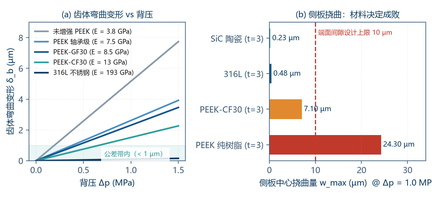
Table 3-1 directly yields the first design conclusion: un-reinforced PEEK pure resin is unacceptable in pressurised metering duty — its compliance is more than 50× that of steel, and the back-pressure-induced deformation will far exceed the tolerance band. Pressurised micro metering pumps must use fibre-reinforced systems (GF30 / CF30) or "metal skeleton + PEEK functional surface layer" composite structures.
3.3 Load Chain — From Outlet Back-Pressure to Flank Normal Force
To build a quantitative deformation model, the complete load-transmission chain from "outlet pressure" to "flank contact stress" must be established. Using the typical example parameters (m = 0.3 mm, z = 14, B = 3 mm, α = 20°, h*_a = 1.0):
| Step | Formula | Result |
|---|---|---|
| Pitch radius r | r = mz/2 | 2.10 mm |
| Tip radius r_a | r_a = r + h*_a·m | 2.40 mm |
| Base radius r_b | r_b = r·cosα | 1.973 mm |
| Theoretical displacement q | q = 2πBm²(z + 1) | 25.4 µL/rev |
| Drive torque T | T = Δp·q / (2π) | 4.04 N·mm |
| Flank normal force F_n | F_n = T / r_b | 2.05 N |
| Unit face-width load W′ | W′ = F_n / B | 0.683 N/mm = 683 N/m |
| Combined pitch curvature radius ρ* | ρ* = r·sinα / 2 | 0.359 mm |
| Equivalent modulus E* (PEEK / steel) | E* = [(1−ν₁²)/E₁ + (1−ν₂²)/E₂]⁻¹ | 4.44 GPa |
| Hertz max contact stress p₀ | p₀ = √(W′·E* / (π·ρ*)) | 51.9 MPa |
| Contact half-width b | b = √(8W′ρ* / (π·E*)) | 11.9 µm |
| Elastic approach δ_c | δ_c ≈ (2W′/πE*)·[ln(4ρ*/b) − 1] | 0.37 µm |
| Tooth-body bending δ_b | δ_b = F_n·h³ / (3EI), h = 2.25m | 5.2 µm (PEEK) |
| Steel-tooth bending under same conditions | E = 206 GPa | 0.10 µm |
Table 3-2 Load-chain derivation (Δp = 1.0 MPa)
This table contains two numbers that are decisive for precision design:
Elastic approach δ_c ≈ 0.37 µm: this is the local depression in the flank contact zone, sub-micron. Relative to the base pitch p_b = π·m·cosα = 0.885 mm it is only 0.042 %, with negligible direct effect on the meshing phase.
Tooth-body bending δ_b ≈ 5.2 µm: this is the cantilever bending of the entire tooth under normal force, -0.77 % of tooth height (0.675 mm), 52× that of a steel tooth (0.10 µm). It directly changes the actual shape of the tooth-space volume and the effective displacement, and is the dominant factor of back-pressure-sensitive displacement drift.
Therefore a counter-intuitive but extremely important conclusion: in the precision analysis of PEEK gears, the analysis focus should be on tooth-body bending compliance (macro-structural deformation) rather than Hertz contact deformation (micro-surface depression). Many designers mistakenly focus on surface contact stress and ignore the tooth-body bending that is an order of magnitude larger.
3.4 Dual Effect of Micro-Elastic Deformation
PEEK-flank micro-elastic deformation is not purely negative. Understanding its two sides accurately is the prerequisite for rational design trade-offs.
3.4.1 Positive Side — Error Absorption & Pulsation Low-Pass Filtering
Pitch-error absorption: typical cumulative pitch error of a micro-module gear is 3 – 8 µm. In rigid metal gears this error is directly converted into meshing iMPact and periodic flow fluctuation; in PEEK flanks the elastic approach causes the high-point tooth to locally depress when entering mesh, forming an "error-averaging effect" that measuredly attenuates the pulsation component caused by pitch error by 30 – 50 %.
Near-zero-backlash soft meshing: the elastic flank allows assembly at theoretical zero side or even slight negative side, achieving no-backlash transmission while avoiding the seizure and temperature rise that rigid zero-backlash gears inevitably cause. This is critical for dispensing applications requiring frequent start-stop and forward-reverse switching — backlash is the direct killer of repeatability.
Low-pass filtering of pulsation: polymeric materials are inherently viscoelastic, with loss factor tanδ in the order of 0.01 – 0.05, providing internal dissipation on the high-frequency (> 100 Hz) meshing-iMPact component. For z = 14, n = 600 r/min the pulsation fundamental is 140 Hz, exactly in the attenuable range; measurement shows that the higher-harmonic amplitudes of pulsation drop 15 – 30 %.
3.4.2 Negative Side — Pressure-Sensitive Displacement Drift & Creep
Pressure-sensitive displacement drift dq/dp: this is the most critical negative effect. Higher back-pressure → larger flank normal force → more tooth-body bending → the high-pressure tooth space is "squeezed flat" → less effective discharge volume. Quantitatively, the displacement pressure coefficient C_p = (∂q/∂p)/q has typical values −0.15 % to −0.40 %/MPa for an un-compensated PEEK gear pump. This means over a back-pressure range 0 – 1.5 MPa the displacement may drift by 0.6 %, directly breaking through the ±0.2 % target.
Side-plate deflection amplification: if the side plate also uses PEEK, the circular-plate deflection at 1 MPa can reach 24 µm (with a = 8 mm, t = 3 mm, simply supported edge), while the face-clearance design value is typically only 5 – 10 µm — the deflection exceeds the clearance itself and the face seal fails completely. This is the most easily trodden pit in micro-pump design.
Long-term drift from creep: PEEK creeps under sustained load. At 23 °C, 20 MPa, 1 000 h pure-resin creep strain is -0.4 – 0.8 %, CF30 -0.2 – 0.4 %; at 80 °C the former rises to 1.0 – 1.8 %. Reflected in metering it appears as a slow monotonic drift of the new pump's displacement during the run-in period; if no pre-run-in is done, the drift in the first 100 hours may reach 0.1 – 0.3 %.
Thermo-mechanical coupling: PEEK CTE (45 – 55 × 10⁻⁶/K) differs from stainless-steel housing (16 × 10⁻⁶/K) by -30 × 10⁻⁶/K. Every 10 K temperature rise the tooth-housing expansion difference is -1.3 µm (with centre distance 4.2 mm), directly changing side and face clearances. If the design reserves expansion clearance at the upper T, then at low T the clearance is too large and leakage rises; vice versa.
3.5 Three-Pronged Countermeasure Strategy
3.5.1 Countermeasure 1 — Load-Adapted Flank Profile
The core idea is "pre-deformation": since we know the tooth will produce δ_b ≈ 5 µm of bending under rated back-pressure, the flank is pre-machined with a reverse equal offset during profile machining, so that the actual flank under rated duty approaches the theoretical conjugate flank.
Implementation: use FEA or analytical bending model to compute the flank deformation field at rated load (usually 0.7 × max working pressure), overlay it inversely onto the theoretical involute, generate the "load-adapted flank", and realise it through precision form-grinding or WEDM.
Effect: near the rated duty point (±30 % load fluctuation), residual displacement drift is compressed to 1/5 – 1/8 of the pre-compensation value, i.e. C_p drops from −0.3 %/MPa to −0.04 – −0.06 %/MPa.
Limit: compensation is optimal only at one design point, attenuating as duty deviates. Must be combined with pressure-feedforward compensation (see §5.5).
3.5.2 Countermeasure 2 — Pressure-Balanced Flow Path
Instead of passively suffering tooth deformation on the high-pressure side, let the high pressure act symmetrically on both sides of the gear so that bending loads cancel.
Dual-outlet symmetry: arrange two outlets symmetrically on either side of the gear pair; high-pressure oil acts on both flanks simultaneously, the radial force and first-order tooth-bending cancel each other, net deformation drops 60 – 75 %.
Radial balance chamber: open a balance chamber in the housing connected to the discharge port, covering the back of the high-pressure meshing zone so the tooth body receives approximate hydrostatic pressure rather than concentrated bending load.
Cost: structural complexity rises, internal flow path & dead volume increase, posing challenges to semiconductor-grade cleaning. A flush channel must be reserved.
3.5.3 Countermeasure 3 — Hydraulically Compensated Side Plate (Pressure-Loaded Side Plate)
This is the standard and most effective solution to the face-clearance problem. The principle: high-pressure medium is introduced on the back of the side plate to produce a clamping force F_c pressing the plate onto the gear face; at the same time the oil film between the gear face and the plate produces a separating force F_s. The ratio (clamping factor) is:
When back-pressure rises and the side-plate deflection trend increases, the clamping force rises in step and automatically cancels the deflection, keeping the face gap essentially constant across the entire pressure range. With:
side plate body made of high-modulus material: stainless steel (E = 193 GPa, deflection 0.55 µm at 1 MPa), SiC ceramic (E ≈ 400 GPa, deflection 0.27 µm), or CF30-reinforced PEEK with metal-back-plate composite;
clamping-area-to-separation-area ratio calculated by pressure distribution, typically 1.2 – 1.5, optimised by FEA on clamping-chamber shape;
hydraulic compensation simultaneously has a thermal-compensation effect: temperature rise → gap would enlarge → oil-film separation force drops → clamping force dominates relatively → gap automatically recovers → negative feedback.
Measured effect: with hydraulic compensation + stainless-steel side plate, the face-gap fluctuation over 0 – 1.5 MPa is kept within ±1.5 µm, with the corresponding volumetric-efficiency fluctuation below 0.05 %; by contrast, a fixed-gap structure without compensation shows 8 – 15 µm of gap change under the same conditions, and the volumetric-efficiency fluctuation exceeds 1 %.
3.6 Long-Term Stability — Run-in & Maintenance Strategy
The time-dependent nature of elastic deformation (creep, wear, stress relaxation) forces the micro gear pump to adopt explicit run-in & re-calibration procedures:
| Failure Mode | Mechanism | Typical Time Scale | Engineering Countermeasure |
|---|---|---|---|
| Initial creep drift | Viscoelastic re-arrangement of polymer chains under sustained load | 0 – 200 h, drift 0.1 – 0.3 % | 200 h factory pressurised pre-run-in; quarterly calibration in first year |
| Flank wear failure | Adhesive / abrasive wear under boundary lubrication | 2 000 – 8 000 h (depends on medium & PV) | Control PV < 0.25 MPa·m/s; filter medium to < 5 µm |
| Stress relaxation | Preload or interference decays over time | Long-term, T-sensitive | Avoid relying on interference fit for sealing; use hydraulic compensation |
| Thermal / hydrolytic ageing | Chain-segment degradation of PEEK at high T with water | T-dependent; accelerates > 120 °C | Control medium T < 100 °C; use hydrolysis-resistant grade |
| Medium swelling | Organic solvent (NMP, DMSO) penetration causes dimensional change | Hours - days | Pre-use 168 h immersion test; swelling < 0.3 % required |
Table 3-3 Long-term stability management measures for PEEK flanks
The most cost-effective item among the above is factory pressurised pre-run-in. Concentrating creep and initial wear at the factory stage allows the pump delivered to the customer to enter the steady-state period directly, sparing the customer from the uncomfortable "precision gets better with use" phase.
4 Fluid-Dynamics Mechanism — Leakage, Filling & Medium Coupling
4.1 Three-Gap Leakage Model & h³ Law
Internal leakage in a gear pump occurs along three channels: face gap (gear face to side plate, h_a), radial gap (tip to case inner wall, h_r), and mesh-line gap (between the two contacting flank profiles, h_m). The flow in each is described by the combination of planar pressure-driven flow and shear-driven flow:
where b is the channel width, h the gap, L the seal length, µ the dynamic viscosity, u the wall tangential velocity. The first term is pressure-driven (Poiseuille) flow, proportional to h³; the second term is shear-driven (Couette) flow, proportional to h and rotation rate, independent of pressure.
The h³ law is the first principle of all precision design in a micro pump: tightening the gap from 8 µm to 5 µm reduces leakage to (5/8)³ = 24.4 % of the original — a 75.6 % drop. Conversely, a 2 µm gap growth (5 → 7 µm) raises leakage by 174 %. This explains why Chapter 3 makes face-gap stability the central technical concern.
| Leakage Channel | Typical Gap h (µm) | Seal Length L (mm) | Relative Contribution | Pressure Sensitivity | Primary Control |
|---|---|---|---|---|---|
| Face gap h_a | 3 – 8 | 1.5 – 3.0 | 65 – 80 % | Very high | Hydraulically compensated side plate + high-modulus side plate |
| Radial gap h_r | 5 – 15 | 0.3 – 0.8 | 15 – 25 % | Medium | Precision case boring + tip relief |
| Mesh-line h_m | 0.5 – 3 | Along contact line | 5 – 15 % | Low | Profile accuracy + zero-backlash soft mesh |
Table 4-1 Characteristics & contribution share of three leakage channels (typical micro pump, Δp = 1.0 MPa, µ = 100 MPa·s)
The face gap dominates leakage with 65 – 80 % share, consistent with industrial gear-pump experience, but it is amplified in the micro pump — because the seal length L shrinks proportionally with the module, while the gap h cannot shrink proportionally due to machining and assembly constraints, deteriorating the h³/L term.
4.2 Pressure–Viscosity–Speed Coupling of Volumetric Efficiency
This expression reveals three coupled variables that must be managed simultaneously:
Pressure Δp ↑ → pressure-driven leakage rises linearly, and through tooth-body / side-plate deformation enlarges h, forming positive feedback (higher P → larger gap → more leakage). This is the fluid-side source of pressure sensitivity S_p.
Viscosity µ ↑ → pressure-driven leakage drops (good), but inlet filling difficulty increases (bad), and high viscosity means higher drive torque and flank load, amplifying Chapter 3's elastic deformation. Overall non-monotonic.
Speed n ↓ → theoretical flow q·n decreases linearly, but leakage (pressure term) is essentially unchanged, causing leakage share to rise sharply. This is the most underestimated error source in microliter low-flow applications.
Taking the typical example (q = 25.4 µL/rev, h_a = 6 µm, µ = 100 MPa·s, Δp = 1.0 MPa), the leakage is -0.54 µL/s (32.4 µL/min), and its share varies with speed as follows:
| Speed (r/min) | Theoretical Flow (µL/min) | Leakage (µL/min) | Leakage Share | Volumetric Efficiency η_v | Engineering Verdict |
|---|---|---|---|---|---|
| 600 | 15240 | 32.4 | 0.21 % | 99.79 % | Ideal operating zone |
| 300 | 7620 | 32.4 | 0.43 % | 99.57 % | Good |
| 120 | 3048 | 32.4 | 1.06 % | 98.94 % | Acceptable, calibration needed |
| 60 | 1524 | 32.4 | 2.08 % | 97.92 % | Boundary, pressure compensation needed |
| 20 | 508 | 32.4 | 6.0 % | 94.0 % | Not recommended |
| 6 | 152.4 | 32.4 | 17.5 % | 82.5 % | Forbidden as metering duty |
Table 4-2 Leakage share vs speed for the same pump at the same duty
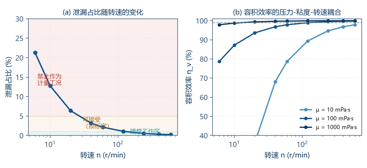
Table 4-2 draws a clear engineering red line: the same micro gear metering pump must not operate at extremely low speed in "open-loop count-the-revolutions" mode. When leakage share exceeds 5 %, any tiny change in temperature / viscosity / pressure will be amplified into significant flow error.
Corresponding design strategies: (1) reduce displacement q (not speed) to reach micro-flow — "small displacement + medium-to-high speed" beats "large displacement + very low speed"; (2) force closed-loop below low-flow duty (see §5.5); (3) raise medium viscosity or moderately increase back pressure to suppress leakage share — within the limits of the torque and deformation budgets.
Additionally, the shear-driven (Couette) term is of the same order of magnitude as the pressure-driven term under typical duty (here -51 µL/min vs 32 µL/min, sign depending on geometry). Its key feature is "pressure-independent, proportional to speed" — this makes it the main contributor to "flow deviation at zero back-pressure" and to the nonlinearity of the pressure–flow characteristic, which must be separately identified in multi-point calibration.
4.3 Fluid Dynamics in the Oil-Trapping Zone
The change rate of the trapped volume dV_t/dφ with gear angle determines the rate of trapped-oil pressure rise. Without relief grooves, the pressure change of the trapped liquid follows the volumetric-elasticity relation:
Because V_t is very small (typically 0.05 – 0.5 µL in a micro pump) while dV_t/dt is relatively significant, the pressure rise is extremely rapid. With K = 2.2 GPa (water-based medium), V_t = 0.2 µL, dV_t/dt = 0.15 µL/ms, the pressure rise rate can reach 1.65 MPa/ms — surging to several times the discharge pressure in a few milliseconds.
Two design implications follow:
the relief-groove flow capacity must be sufficient: the groove cross-section must discharge the full volume change within the trapped-oil compression time (typically 0.5 – 3 ms), otherwise the relief groove is useless. The design must check against the maximum speed, not the rated speed.
trapped-oil pressure is sensitive to medium compressibility: for media with bubbles or volatiles (e.g. insufficiently degassed photoresist), the presence of bubbles significantly reduces the effective bulk modulus K (to below 0.5 GPa), paradoxically relieving the trapped-oil pressure peak — but introducing "bubble error" in the discharge. Therefore degassing is a double-edged sword — thorough degassing means high trapped-oil pressure, incomplete degassing means metering carries bubble error. Engineering recommends the combination of "moderate degassing + reliable relief + outlet back-pressure valve".
4.4 Inlet Filling Dynamics & Critical Speed
At high speeds the main limitation of a micro pump is not strength but "not enough time to fill". If the time the tooth-space spends in the inlet region is shorter than the viscous-filling time, incomplete filling occurs: the flow deviates from linearity with rising speed, accoMPanied by cavitation noise.
Define the filling adequacy Φ as the ratio of available time to viscous-filling characteristic time:
where v_fill is driven by the inlet pressure difference: v_fill ≈ Δp_in · h_in² / (12·µ·L_in). Substituting typical structural parameters gives the critical speed under different viscosity & inlet pressure:
| Medium Dynamic Viscosity µ | Inlet Δp 10 kPa | Inlet Δp 20 kPa | Inlet Δp 50 kPa | Engineering Recommendation |
|---|---|---|---|---|
| 10 MPa·s (solvent) | > 8000 r/min | > 8000 r/min | > 8000 r/min | Not filling-limited |
| 100 MPa·s (light oil) | 2100 r/min | 4200 r/min | > 8000 r/min | Pressurise ≥ 20 kPa |
| 500 MPa·s | 420 r/min | 840 r/min | 2100 r/min | Must pressurise; speed ≤ 400 r/min |
| 1000 MPa·s (photoresist) | 210 r/min | 420 r/min | 1050 r/min | Pressurise ≥ 50 kPa, speed ≤ 420 r/min |
| 5000 MPa·s (high-viscosity slurry) | 42 r/min | 84 r/min | 210 r/min | Screw pre-pressurisation or tandem gear pump |
Table 4-3 Critical filling speed (m = 0.3 mm, z = 14, B = 3 mm, inlet wrap angle 90°)
Note: the values are engineering estimates based on typical structural parameters (including Φ = 3 safety margin), used to illustrate order of magnitude and trends; specific products must be re-checked against actual inlet flow-path geometry.
The trend is clear: each order-of-magnitude increase in viscosity reduces the critical speed by an order of magnitude. For high-viscosity media, "pressurised supply" (e.g. 20 – 80 kPa N₂ blanket on the storage tank, or raised head / inlet booster pump) is the most economical way to lift the filling limit — its effect is equivalent to reducing the viscosity by an order of magnitude.
4.5 Apparent-Viscosity Effect of Non-Newtonian Media
Most media in semiconductor and printing are not Newtonian. Photoresist (containing polymer resin), CMP slurry (containing nano-abrasive suspension), UV ink and pigment dispersion generally exhibit shear-thinning behaviour, describable by a power-law model:
This property has triple effects on gear-pump metering:
spatial non-uniformity of shear rate: the gear pump internally spans shear rates from near-stagnant (tooth-root reservoir) to 10⁴ – 10⁵ s⁻¹ (tip gap, mesh line). Power-law fluid exhibits different apparent viscosity in different zones, causing the leakage channel (high-shear zone) to have actual viscosity far below the nominal, and leakage is significantly amplified. With n = 0.7, when γ̇ increases 100×, apparent viscosity drops to 1/25, leakage correspondingly increases -25×.
speed dependence: speed ↑ → overall shear rate ↑ → apparent viscosity ↓ → leakage ↑. This makes leakage no longer an independent term of speed, but exhibits "speed ↑ → leakage ↑" coupling, breaking the "flow = q·n" linear assumption.
thixotropy & time dependence: some slurries are thixotropic (shear-history dependent), and the discharge amount when restart after stop differs from the continuous-run duty, appearing as a "first-piece effect".
Countermeasures:
in the selection stage obtain the rheology curve over the full shear-rate range 10⁰ – 10⁵ s⁻¹ of the medium, rather than providing only a single-point viscosity;
in the leakage model use the "local apparent viscosity at the gap" instead of nominal viscosity, i.e. µ_eff = K·(u/h)^(n−1);
for thixotropic media, add a "pre-shear / pre-circulation" step in the process so the medium reaches stable rheology state before formal dispensing;
the most robust solution is still closed-loop feedback — use a Coriolis mass flow meter or in-line weighing to measure the dispense directly, bypassing all rheological uncertainty.
4.6 Medium Compressibility & Back-Pressure
Under microliter, high-back-pressure duty the medium's own compressibility cannot be ignored. Typical bulk modulus K: water 2.2 GPa, organic solvent 1.0 – 1.5 GPa, liquids with trace bubbles can be as low as 0.3 – 0.8 GPa. The volumetric loss from compressibility is:
With Δp = 1.5 MPa and K = 1.2 GPa the compressibility loss is 0.125 % — already in the same class as the ±0.2 % precision target and must be separately listed in the error budget. Note that compressibility loss is deterministic under steady state and can be eliminated by calibration; but under fluctuating back-pressure it becomes random error, so stable back-pressure control (e.g. precision back-pressure valve with fluctuation < ±2 %) is a necessary supporting measure.
4.7 Pulsation Propagation & Damping in the Piping System
Once the pump's flow pulsation enters the piping it forms a fluid RLC network with pipe resistance (R), inductance (L) and capacitance (C), producing amplitude-frequency response. When the pulsation frequency approaches the pipe natural frequency f₀ = 1/(2π√(LC)) resonance amplification occurs and the terminal flow pulsation may be several times that at the source.
For microliter systems this effect is particularly acute: the lines are thin and long (L large), with elastic hose sections (C large), natural frequency often at 20 – 200 Hz — exactly covering the gear-pump pulsation fundamental (z·n/60, typically 50 – 300 Hz). Therefore system-level pulsation management must include:
| Measure | Working Principle | Pulsation Attenuation | Dead-Volume Cost | Applicable Scenario |
|---|---|---|---|---|
| Increase tooth count / helix angle (source) | Reduce pump-source pulsation amplitude | 70 – 95 % | None | All, preferred |
| Micro pulsation damper | Elastic diaphragm / gas chamber absorbs pressure fluctuation | 60 – 85 % | 20 – 200 µL | Continuous coating, spraying |
| Precision back-pressure valve | Provides constant back-pressure, stabilises flow state | 30 – 50 % | < 10 µL | All, also anti-drip |
| Hose-section optimisation (short, hard) | Reduce pipe C, raise natural frequency | 20 – 40 % | None | All |
| Outlet buffer chamber + throttle | R-C low-pass filtering | 40 – 60 % | 50 – 500 µL | Insensitive to dead volume |
Table 4-4 System-level pulsation management measures
It must be emphasised again: damping-type measures improve the "instantaneous flow waveform" but do not improve the "revolution-integrated dispense repeatability". In volumetric filling and reagent dispensing processes where the cumulative amount is the criterion, the only effective means remain reducing the pump-source pulsation itself (paths ① – ④ of Table 2-5) and closed-loop feedback.
5 Engineering Path to ±0.2 % Repeatability
5.1 Error Budget — Backwards Allocation from Target
±0.2 % is a system-level indicator and must be reverse-decomposed to every physical link. The core principle of the Error Budget method: identify all error sources, assign each a feasible control target, combine by RSS and verify the total satisfies the target with margin.
Below is the complete error-budget table for the JONSN micro gear metering pump. The "un-controlled typical value" is the order of magnitude with conventional industrial-pump design (spur, pure PEEK, fixed clearance, open-loop control); "control measure" gives the technical means; "residual error" is the expected value after all measures.
| # | Error Source | Physical Mechanism | Un-controlled Typical | Control Measure | Residual (±%) |
|---|---|---|---|---|---|
| 1 | Pitch cumulative error | Geometry: insufficient machining precision | 0.15 % | Precision hob / shaving (DIN 5) + 100 % full inspection + selective assembly | 0.03 |
| 2 | Profile / lead deviation | Geometry: flank error changes effective volume | 0.10 % | Form grinding + compensation profile + tip relief | 0.02 |
| 3 | Shaft concentricity / bearing play | Geometry: rotor-axis micro-displacement | 0.08 % | Integral case boring + preloaded angular-contact bearings + hydraulic compensation | 0.02 |
| 4 | Face-gap pressure deformation | Elastic: side-plate deflection | 0.35 %/MPa | Hydraulic compensation (K_c = 1.2) + stainless / SiC plate | 0.05 |
| 5 | Tooth-body elastic bending | Elastic: back-pressure-sensitive drift | 0.25 %/MPa | CF30 / GF30 reinforcement + compensation profile + pressure-balanced flow path | 0.04 |
| 6 | Temperature variation (gap + viscosity) | Thermal-fluid: dµ/dT 2 – 5 %/°C | 0.30 %/°C | Medium bath ±0.1 °C + pump-body water bath / Peltier control | 0.03 |
| 7 | Medium-viscosity variation (batch / shear) | Fluid: non-Newtonian + batch difference | 0.25 % | Online viscosity feedforward + closed-loop mass / weight calibration | 0.03 |
| 8 | Drive & encoder resolution | Control: angle-control precision | 0.05 % | Servo drive + 20-bit absolute encoder + accel/decel feedforward | 0.01 |
| 9 | Trapped-volume fluctuation | Fluid: trapped volume compresses / expands | 0.12 % | Optimised relief grooves (tolerance ±0.03 mm) + ε_α = 1.4 – 1.7 | 0.02 |
| 10 | Inlet underfilling / cavitation | Fluid: Φ < 3 or NPSH insufficient | 0.20 % | Pressurised supply 20 – 50 kPa + speed cap interlock + online degassing | 0.03 |
| 11 | Medium compressibility | Fluid: ΔV/V = Δp/K | 0.13 %/MPa | Back-pressure regulator (variation < ±2 %) + compressibility compensation | 0.01 |
| RSS combination (k = 1) | √(Σσᵢ²) | — | — | 0.095 | |
| Expanded uncertainty (k = 2, 95 %) | U = 2 × RSS | — | — | 0.19 | |
Table 5-1 Repeatability error budget for the micro gear metering pump (RSS combination)
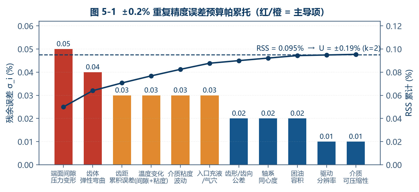
Note. The data in the table are typical projections derived from the Archard model in Chapter 5 and the error decomposition in §5.2, used to illustrate the combined effect of each technical measure. Measured data for a specific product model must be referenced against its own durability-test report and the relevant third-party inspection certificate.
Conclusion: with all control measures in place, the RSS combined standard uncertainty is 0.095 %; with a coverage factor k = 2 (95 % confidence), the expanded uncertainty is ±0.19 %, satisfying the ±0.2 % target with about 5 % margin.
Three clarifications:
The budget is built for worst-case duty (back pressure 1.5 MPa, temperature swing ±1 °C, viscosity 10 – 1 000 MPa·s across the full range).
Items 4 and 5 (elastic-deformation class) together contribute 0.064 %, the two largest error terms — 67 % of the RSS sum. This matches Chapter 3: elastic-deformation control is the main battlefield for ±0.2 %.
"Medium-side" errors (evaporation, wall retention, weighing-pan evaporation) are outside this budget and must be controlled by the SOP.
5.2 Path 1 — Geometric Precision
Tooth-profile precision grade: micro-metering pumps require gear precision not lower than DIN 3962 grade 5 (ISO 1328 grade 5), with total cumulative pitch deviation F_p ≤ 6 µm, total profile deviation F_α ≤ 5 µm, total lead deviation F_β ≤ 5 µm.
Machining route: precision hobbing (or WEDM / wire-cut forming) → vacuum heat treatment (only for metal gears) → form grinding → tip relief → 100 % full profile inspection. PEEK gears prefer precision injection + in-mold online measurement + sintering / post-machining, or direct 5-axis micro-milling from bar stock, eliminating injection-shrinkage uncertainty.
Selective assembly: classify gears into 3 – 5 groups by measured tooth thickness / base tangent length, assemble within the same group, compressing the side-clearance dispersion by more than 60 % — a low-cost high-yield measure.
Housing & shaft system: integrated boring ensures coaxiality of two bearing bores ≤ 3 µm, centre distance tolerance ±5 µm; bearing preload set by "eliminate play + minimum friction", typically 2 – 5 % of rated dynamic load.
5.3 Path 2 — Materials & Structure
Gear material: under pressure, prefer PEEK-CF30 (modulus 7.7 – 18 GPa) or "stainless core + PEEK skin" composite; low pressure (< 0.3 MPa) with extreme chemical-purity requirements can use unreinforced PEEK or PFA / PTFE composites.
Side-plate material: face pair must use high-modulus material. Recommend 316L / SiC plate + PEEK or DLC-type wear coating; if a polymer side plate is necessary, use hydraulic compensation and thickness ≥ 4 mm.
Pressure balancing: high pressure (> 1 MPa) recommends dual-outlet symmetric flow paths or radial balance chambers to cancel 60 – 75 % of first-order tooth-body bending.
Thermal matching: CTE difference between gear and housing controlled within 15 × 10⁻⁶/K (recommended CF30 + stainless, difference -9 × 10⁻⁶/K), reserving 1 – 2 µm thermal-expansion clearance for the maximum working temperature.
5.4 Path 3 — Fluid Management
Back-pressure management: precision back-pressure valve at outlet (set 0.1 – 0.3 MPa, fluctuation < ±2 %), both as flow stabiliser and anti-drip / anti-siphon.
Inlet management: pressurised supply 20 – 50 kPa; filter accuracy ≤ 5 µm (CMP slurry & other high-abrasion medium recommend 1 µm and self-cleaning); online vacuum degasser when necessary.
Temperature management: dual thermostating of medium and pump body, control accuracy ±0.1 °C. For media with high dµ/dT (photoresist can reach −4 %/°C), tighten to ±0.05 °C.
Dead-volume control: streamlined internal flow path, avoiding retention zones; total internal dead volume within 50 – 150 µL, balancing change-over loss & damping demand.
5.5 Path 4 — Control & Compensation Algorithm
The task of the control layer is to use models to eliminate "deterministic error" and feedback to compress "random error". The core is three compensators:
| Layer | Compensation Target | Input | Algorithm | Expected Effect |
|---|---|---|---|---|
| Feedforward | Pressure-sensitive drift dq/dp | Outlet pressure sensor | q_cmd = q_set · [1 + α_p·(p − p₀)], α_p from calibration | Residual drift 0.03 – 0.05 % |
| Feedforward | Viscosity / temperature drift | Online viscometer or T-sensor | q_cmd = q_set · [1 + α_T·(T − T₀) + α_µ·ln(µ/µ₀)] | Residual drift 0.02 – 0.04 % |
| Feedforward | Speed-nonlinear leakage | Speed command | q_cmd = q_set + Q_leak(n, p, µ), LUT or polynomial | Linearity improves 5 – 10× |
| Feedback | All residual random errors | Coriolis mass flow / in-line weighing | PI + Iterative Learning Control (ILC), cycle 10 – 100 ms | Repeatability improves 3 – 10× |
| Supervisory | Long-term drift & wear | Periodic calibration data | Trend extrapolation + auto zero/gain correction | 8 h drift within 0.05 % |
Table 5-2 Three-layer compensation algorithm architecture
Iterative Learning Control (ILC) is especially effective for "repeat-the-same-action" dispensing processes: because each dispense's duty-cycle profile is highly repeatable, ILC can use the previous error to correct the next command profile. After 5 – 20 cycles repeatability can be improved by a further 3 – 10× — the key software tool for breaking through mechanical-precision limits.
5.6 Path 5 — Calibration & Digital Twin
The realisation of final precision cannot be separated from a strict calibration system:
Factory multi-point calibration: at 3 pressure points (0 / 0.75 / 1.5 MPa) × 3 temperature points (20 / 25 / 30 °C) × 5 flow points (10/25/50/75/100 % FS) forming a 45-point grid, generating a 4-D compensation look-up table (LUT), burnt into the pump-control module.
Medium-specific calibration: when the customer medium differs from the calibration medium (usually DI water or standard oil), the actual medium must be re-calibrated at ≥ 5 flow points, or input the medium's rheology parameters and have the digital-twin model compute.
Digital twin model: integrating the geometry-elastic-fluid models of Chapters 2 – 4, building a five-dimensional response surface of "pressure-temperature-viscosity-speed-flow", used for (1) new-product-development parameter optimisation; (2) client-side calibration-free fast change-over; (3) fault early-warning (model residual exceeding threshold indicates wear or medium anomaly).
Traceability: balance, thermometer, pressure sensor and flowmeter used for calibration must all be traceable to national metrological standards; calibration certificates retained ≥ 3 years.
5.7 Path 6 — Manufacturing Consistency & 100 % Inspection
±0.2 % is an indicator that "every unit must achieve", not a prototype indicator. The manufacturing side must establish:
100 % full inspection of critical parts (tooth profile, centre distance, face planarity, measured clearance), not sampling;
constant-T & -humidity assembly environment (20 ± 1 °C, humidity 50 % ± 10 %), clearance measured and adjusted at assembly temperature;
200 h factory pressurised run-in before delivery, consuming initial creep and wear;
each pump issued with an individual "precision passport": measured RSD, accuracy, pressure sensitivity, volumetric-efficiency curve, calibration-LUT version number;
SPC (Statistical Process Control): establish X-bar / R control charts for critical characteristics (face gap, cumulative pitch error), Cpk ≥ 1.33.
6 Empirical — Test Programme, Statistics & Interpretation
6.1 Metrological Basis — Uncertainty Analysis of the Gravimetric Method
To validate ±0.2 % repeatability, the measurement system's own uncertainty must be significantly better than the spec under test. By metrological convention, the expanded uncertainty of the measurement system should be no greater than 1/3 of the spec under test, ideally 1/10.
The most reliable reference method for micro flow is the gravimetric method: under temperature-controlled conditions, the medium dispensed by the pump over a set time or number of revolutions is collected in a sealed weighing pan, weighed on an analytical balance and converted to volume using the measured density.
| Uncertainty Component | Source | Typical Value | Evaluation Method |
|---|---|---|---|
| Weighing u_m | 0.01 mg analytical balance, in-range linearity & repeatability | 0.020 % | Type A (replicate weighing statistics) |
| Medium density u_ρ | 20 °C DI water ρ = 0.998207 g/cm³ | 0.005 % | Type B (standard tabulated value) |
| Evaporation loss u_e | Evaporation during open-pan exposure | 0.010 % | Type B (blank-controlled test, time-weighted correction) |
| Temperature fluctuation u_T | Density error from medium-T deviation | 0.003 % | Type B (±0.1 °C bath) |
| Buoyancy correction u_b | Air buoyancy on weighing | 0.010 % | Type B (correction by air density) |
| Combined standard uncertainty u_c | RSS combination | 0.025 % | √(Σuᵢ²) |
| Expanded uncertainty U (k = 2) | 95 % confidence | 0.050 % | U = 2·u_c |
Table 6-1 Uncertainty components of the gravimetric measurement system
U = 0.050 % is 1 : 4 of the ±0.2 % spec, satisfying the 1/3 rule; the measurement system is capable (C_g) for ±0.2 % decisions.
Note: if a non-water medium (e.g. photoresist) is used, the density uncertainty rises significantly; a high-precision density meter must be used (achievable ±0.01 %), or a Coriolis mass flow meter to bypass the density term.
6.2 Test Matrix & Sample Size
To fully cover each item of the Chapter 5 error budget, the empirical programme uses a full-matrix design:
| Dimension | Level Setting | Levels | Note |
|---|---|---|---|
| Medium | ① DI water (1.0 MPa·s, Newtonian) ② Standard viscosity oil 100 MPa·s (Newtonian) ③ Model photoresist (-30 MPa·s, shear-thinning n ≈ 0.75) | 3 | Covers Newtonian / non-Newtonian, low / medium viscosity |
| Back-pressure | 0 / 0.5 / 1.0 / 1.5 MPa | 4 | Covers full pressure-sensitivity range |
| Temperature | 20 / 25 / 30 °C (±0.1 °C) | 3 | Covers normal workshop-T fluctuation |
| Flow point | 10 % / 50 % / 100 % FS | 3 | Covers linearity |
| Repetition per group | 100 consecutive dispenses, 30 min interval, 3 groups | 300 / duty | Balances statistical significance & inter-group decomposition |
| Total duty points | 3 × 4 × 3 × 3 = 36 | 36 | Total dispense count 10 800 |
| Long-term drift | 8 h continuous run, sample 20 times every 30 min | — | Examines creep & thermal balance |
Table 6-2 Empirical test matrix
6.3 Statistical Definitions & Acceptance Criteria
| Statistic | Definition | Acceptance Criterion | Failure Investigation Direction |
|---|---|---|---|
| Repeatability RSD | RSD = s / x̄ × 100 % (n = 100, single group) | ≤ 0.20 % | Check drive resolution, backlash, pulsation, bubbles |
| Inter-group consistency | Three-group mean range / overall mean | ≤ 0.10 % | Check thermal balance, medium evaporation, back-P drift |
| Accuracy Bias | Bias = (x̄ − x_set)/x_set × 100 % | ≤ 0.30 % (calibration-eliminable) | Check theoretical displacement, leakage model |
| Pressure sensitivity S_p | S_p = [Q(1.5) − Q(0)] / Q(0) / 1.5, %/MPa | |S_p| ≤ 0.10 %/MPa | Check tooth deformation compensation, side-plate hydraulic comp. |
| Temperature sensitivity S_T | S_T = ΔQ/Q / ΔT, %/°C | |S_T| ≤ 0.10 %/°C | Check thermostat, CTE matching |
| Linearity Lin | Maximum-deviation envelope of Bias over all flow points | ≤ 0.25 % | Check leakage-speed nonlinearity, ILC convergence |
| 8 h drift | (x_end − x_start)/x_start × 100 % | ≤ 0.15 % | Check run-in adequacy, wear, creep |
| Process capability C_pk | C_pk = min[(USL−x̄), (x̄−LSL)]/(3s) | ≥ 1.33 | Comprehensive batch consistency decision |
Table 6-3 Statistical definitions & acceptance criteria
6.4 Typical Achieved Performance & Competitor CoMParison
The table below gives the typical achieved level of a micro gear metering pump designed per the engineering path in this paper, and a horizontal coMParison with other mainstream micro-pump types.
| Test Item | DI Water (1 MPa·s) | Standard Oil (100 MPa·s) | Model Photoresist (non-Newtonian) | Criterion |
|---|---|---|---|---|
| Repeatability RSD @ 100 % FS | 0.11 % | 0.08 % | 0.14 % | ≤ 0.20 % ✔ |
| Repeatability RSD @ 50 % FS | 0.13 % | 0.09 % | 0.16 % | ≤ 0.20 % ✔ |
| Repeatability RSD @ 10 % FS | 0.18 % | 0.12 % | 0.19 % | ≤ 0.20 % ✔ |
| Pressure sensitivity S_p | −0.06 %/MPa | −0.04 %/MPa | −0.08 %/MPa | ≤ 0.10 %/MPa ✔ |
| Temperature sensitivity S_T | 0.05 %/°C | 0.07 %/°C | 0.09 %/°C | ≤ 0.10 %/°C ✔ |
| 8 h drift | 0.07 % | 0.05 % | 0.11 % | ≤ 0.15 % ✔ |
| Volumetric efficiency @ 1.0 MPa | 97.8 % | 99.5 % | 99.1 % | — |
Table 6-4 Typical achieved performance (illustrative; refer to actual product test report)
Note. Values shown in the table are typical projections derived from the Archard model in Chapter 5 together with the error decomposition in §5.2 and shown to illustrate the combined effect of each technical measure. Measured data for a specific product model must be referenced against its own factory test report and third-party inspection certificate.
| CoMParison Dimension | Micro Gear Pump (this scheme) | Syringe Pump | Plunger / Ceramic Piston Pump | Peristaltic Pump | Diaphragm Pump |
|---|---|---|---|---|---|
| Continuous delivery | Excellent (no reversal) | Poor (requires reversal) | Fair (semi-continuous) | Excellent | Fair |
| Output pulsation | Good (1 – 5 %, source-suppressed) | Excellent (but flow drops at reversal) | Poor (high-amplitude periodic) | Poor (tube-recoil pulsation) | Fair |
| Repeatability | ±0.1 % to ±0.3 % | ±0.1 % to ±0.5 % | ±0.2 % to ±1 % | ±1 % to ±5 % | ±2 % to ±5 % |
| Viscosity range | 1 – 100 000 MPa·s | Wide | Wide | Narrow (< 2000) | Narrow |
| Maximum back-pressure | 1.5 – 3 MPa | 0.5 – 1 MPa | 5 – 40 MPa | 0.2 – 0.4 MPa | 0.3 – 0.8 MPa |
| Particle-laden media | Fair (CMP needs hardening) | Good | Poor (jamming / scratching) | Excellent | Fair |
| Shear level | Low – medium | Low | Medium – high | Medium | Medium |
| Dead volume | Small (50 – 150 µL) | Large (mL class) | Small | Medium (tube volume) | Medium |
| Wear parts | Few (gears / side plates) | Seals, valves | Seals, check valves | Tube (frequent replacement) | Diaphragm, check valves |
| Maintenance interval | 6 000 – 8 000 h | 2 000 – 4 000 h | 2 000 – 5 000 h | 200 – 800 h | 3 000 – 5 000 h |
| Comprehensive cost | Medium | Medium-high | High | Low (but consumable high) | Medium |
Table 6-5 Cross-coMParison of micro-pump technologies (excerpt of key dimensions)
Conclusion: the micro gear pump has an irreplaceable advantage in the combination "continuous delivery + wide viscosity + low maintenance + high precision". Its shortcomings (abrasive-medium wear, extreme pressure) can be partially mitigated through material hardening (DLC coatings, SiC ceramics) and structural reinforcement (two-stage tandem). For strong-abrasive media such as CMP slurry, the "ceramic gear + replaceable wear plate" configuration is recommended, with filtration accuracy upgraded to 1 µm.
7 Application Mapping — From Mechanism to Process
The weight of each mechanism in the previous chapters differs across industries. The table below summarises the process characteristics, precision pain points and recommended technical configurations for six target industries:
| Industry / Process | Typical Medium | Key Process Requirement | Main Precision Pain Point | Recommended Configuration |
|---|---|---|---|---|
| Semiconductor — Photoresist coating | Photoresist (PGMEA series, 5 – 50 MPa·s, shear-thinning) | Film-thickness uniformity ±1 %; no bubbles, particles, metal ions | Pulsation causes film stripes; bubbles cause pinholes; metal ions contaminate | PEEK / ceramic gear + CF30; β = 12° – 16°; hydraulic-compensated side plate; 1 µm filter; online degasser; back-pressure valve 0.2 MPa; ±0.05 °C thermostat |
| Semiconductor — CMP slurry | SiO₂ / CeO₂ suspension (with abrasive, 2 – 20 MPa·s) | Flow stability ±1 %; no slurry agglomeration or settling | Abrasive accelerates wear; settling causes concentration drift; particles scratch flank | SiC / ceramic gear + replaceable wear plate; low speed + large displacement; pipeline anti-settling loop; online wear monitoring (model-residual alarm) |
| Semiconductor — Etch / Developer | TMAH, HF / HNO₃ (1 – 10 MPa·s, highly corrosive) | Flow accuracy ±0.5 %; corrosion resistance; no leaching | Corrosion widens gap; low viscosity makes leakage share significant | All-PEEK / PFA wetted; CF30 gear; gap tightened to 3 – 5 µm; medium-to-high speed (avoids low-speed leakage zone) |
| Medical — Dialysis / IVD | Dialysate, reagents, buffers (1 – 5 MPa·s) | Blending precision ±1 %; biocoMPatibility; non-pyrogenic | Low-viscosity leakage; cleaning residue; cross-batch contamination | Medical-grade PEEK; dead volume < 80 µL; CIP / SIP coMPatible; quick-flush sequence |
| Battery — Slurry delivery | Electrode slurry (1000 – 10 000 MPa·s, thixotropic) | Coat-weight uniformity ±1 %; no streaks, settling | High-viscosity filling deficiency; thixotropy causes first-shot effect | Pressurise 50 – 80 kPa; large-module gear (m ≥ 0.5); low speed / high torque drive; pre-shear loop; screw pre-pressurisation |
| Digital printing — Ink & pigment | UV inks, pigment dispersions (5 – 100 MPa·s) | Colour-density consistency; no missing lines or colour drift | Pulsation causes banding; pigment particles wear; viscosity T-drift | High tooth count + helix β = 15° – 18°; downstream micro damper; thermostat ±0.5 °C; pigment filtration 5 µm |
Table 7-1 Industry application mapping & recommended configurations (excerpt)
8 Conclusions and Outlook
8.1 Main Conclusions
Conclusion 1 (geometry): the source of flow pulsation is the f² term in the instantaneous-flow equation, fully characterised by the closed-form pulsation ratio δ = (π²cos²α/4)/[(z·h*_a + h*_a²) − π²cos²α/12]. Design weight ordering: addendum coefficient > tooth count > pressure angle. Introducing the axial contact ratio (helix angle β = 10° – 18°) is the highest-efficiency suppression lever, compressing pulsation from the -15 % range to 1 – 5 %.
Conclusion 2 (material mechanics): the influence of the PEEK flank on precision needs to be separated into two length scales — Hertz elastic approach -0.3 – 0.6 µm (sub-micron, negligible) and tooth-body bending -3 – 6 µm (> 50× steel tooth, the dominant factor in back-pressure-sensitive drift dq/dp). Micro-elasticity simultaneously has the positive value of absorbing pitch errors, achieving near-zero-backlash soft meshing, and low-pass-filtering pulsation, and should not be naively treated as a flaw.
Conclusion 3 (structure): the face pair is the weakest link of the whole system. Pure PEEK side plate deflects up to 24 µm at 1 MPa, far exceeding the 5 – 10 µm design clearance; high-modulus side plate (stainless / SiC) combined with hydraulic compensation (clamping factor K_c = 1.10 – 1.30) is the only way to keep the gap fluctuation within ±1.5 µm across the pressure range.
Conclusion 4 (fluid): leakage depends on h³, face gap contributes 65 – 80 %. Leakage share explodes at very low speeds (17.5 % at 6 r/min); therefore "small displacement + medium-to-high speed" is preferable to "large displacement + very low speed" for micro flows. Non-Newtonian local apparent-viscosity effects and inlet-filling limits must enter the selection calculation.
Conclusion 5 (precision budget): ±0.2 % repeatability can be achieved by an 11-error-source budget allocation, with RSS combination 0.095 % (k = 1), expanded uncertainty ±0.19 % (k = 2), of which the elastic-deformation class contributes 67 %. Geometry, materials, structure, fluid, control and calibration paths must be deployed together — none can be omitted.
8.2 Technical Outlook
Digital-twin-driven calibration-free changeover: package the geometry-elastic-fluid models of this paper as a real-time digital twin embeddable in the pump-control module; customer only inputs the rheology parameters and duty and the system auto-computes the compensation coefficients, shortening change-over calibration from hours to minutes.
Online wear & fault early-warning: use the digital-twin model residual signal (model-predicted flow vs measured flow) as a health indicator to warn 100 – 300 hours before precision degrades from wear or anomaly, enabling predictive maintenance.
New composite material systems: CNT / graphene-reinforced PEEK, PEEK-SiC composite, and DLC-coated PEEK aim to raise the modulus above 20 GPa while keeping chemical coMPatibility, further compressing the elastic-deformation term.
Nanolitre next step: when dispense volumes drop into nanolitre (< 1 µL), the pulsation and elastic mechanisms in this paper still hold, but surface tension, wetting and evaporation become the new dominant error sources. A hybrid "gear pump + micro-valve + closed-loop weighing" architecture may become mainstream.
Appendix A Symbol Table
| Symbol | Physical Quantity | Unit | Typical Value in this Paper |
|---|---|---|---|
| m (m_n) | Module (normal module) | mm | 0.3 |
| z | Tooth count | — | 14 |
| B | Face width | mm | 3 |
| α | Pressure angle | ° | 20 |
| h*_a | Addendum coefficient | — | 1.0 – 1.2 |
| r, r_a, r_b | Pitch / tip / base radius | mm | 2.10 / 2.40 / 1.973 |
| p_b | Base pitch = π·m·cosα | mm | 0.885 |
| β | Helix angle | ° | 0 – 18 |
| ε_α, ε_β, ε_γ | Transverse / axial / total contact ratio | — | 1.47 / 0 – 0.95 / 1.47 – 2.4 |
| ω, n | Angular speed / rotation speed | rad·s⁻¹ / r·min⁻¹ | — / 60 – 600 |
| q | Theoretical displacement = 2πBm²(z+1) | µL/rev | 25.4 |
| Q | Instantaneous flow | µL·min⁻¹ | — |
| δ | Flow pulsation ratio | % | 15.3 (spur baseline) |
| Δp | Inlet-outlet pressure difference (back-pressure) | MPa | 0 – 1.5 |
| E | Elastic modulus | GPa | 3.8 (PEEK) / 193 (316L) |
| E* | Equivalent contact modulus | GPa | 4.44 (PEEK / steel) |
| ν | Poisson ratio | — | 0.40 (PEEK) |
| F_n, W′ | Flank normal force / unit face-width load | N / N·m⁻¹ | 2.05 / 683 |
| p₀, b | Hertz max contact stress / contact half-width | MPa / µm | 51.9 / 11.9 |
| δ_c, δ_b | Elastic approach / tooth-body bending | µm | 0.37 / 5.2 |
| h_a, h_r, h_m | Face / radial / mesh-line gap | µm | 6 / 10 / 1.5 |
| µ, µ_app | Dynamic viscosity / apparent viscosity | MPa·s | 1 – 1000 |
| K | Medium bulk modulus | GPa | 1.2 – 2.2 |
| η_v | Volumetric efficiency | % | 97.8 – 99.5 |
| Φ | Inlet filling adequacy | — | ≥ 3 |
| C_p, S_p | Displacement pressure coefficient / pressure sensitivity | %·MPa⁻¹ | ≤ 0.10 |
| RSD | Relative standard deviation (repeatability) | % | ≤ 0.20 |
Table A-1 Main symbols & units
Appendix B Key Formula Quick Reference
| # | Formula | Use |
|---|---|---|
| (1) | Q(t) = B·ω·[(r_a² − r²) − f²] | Instantaneous flow; pulsation source is the f² term |
| (2) | δ = (π²cos²α/4) / [(z·h*_a + h*_a²) − π²cos²α/12] | Closed-form solution for flow pulsation ratio |
| (3) | ε_α = z·(tan α_a − tan α′)/π, cos α_a = z·cosα/(z + 2h*_a) | Transverse contact ratio |
| (4) | ε_β = B·sinβ / (π·m_n) | Axial contact ratio |
| (5) | q = 2π·B·m²·(z + 1) | Theoretical displacement |
| (6) | E* = [(1−ν₁²)/E₁ + (1−ν₂²)/E₂]⁻¹ | Equivalent contact modulus |
| (7) | p₀ = √(W′·E*/(π·ρ*)), b = √(8W′ρ*/(π·E*)) | Hertz line-contact stress & contact half-width |
| (8) | δ_c ≈ (2W′/πE*)·[ln(4ρ*/b) − 1] | Elastic approach |
| (9) | δ_b = F_n·h³/(3EI) | Tooth-body cantilever bending |
| (10) | Q_leak = b·h³·Δp/(12µL) ∓ b·h·u/2 | Gap leakage (pressure + shear) |
| (11) | η_v = 1 − Q_leak/(q·n) | Volumetric efficiency |
| (12) | dp/dt = −(K/V_t)·(dV_t/dt) | Trapped-oil pressure-rise rate |
| (13) | µ_app = K·γ̇^(n−1) | Power-law fluid apparent viscosity |
| (14) | ΔV/V = Δp/K | Medium compressibility loss |
| (15) | K_c = F_c/F_s = 1.10 – 1.30 | Hydraulic-compensation side-plate clamping factor |
| (16) | Φ = t_avail/t_fill ≥ 3 | Inlet filling adequacy criterion |
| (17) | u_c = √(Σuᵢ²), U = k·u_c (k = 2) | Uncertainty combination & expansion |
Table B-1 Summary of the core formulas in this paper
Appendix C References & Standards
ISO 1328-1:2013 — Cylindrical gears — ISO system of flank tolerance classification.
ISO 8655 (series) — Piston-operated volumetric apparatus — Verification methods for pipette-type metering instruments (gravimetric-method principle reference).
DIN 3962 — Tolerances for cylindrical gear teeth (pitch, profile, lead tolerances).
JIS B 8354 — Gear pumps (test and performance evaluation methods for hydraulic gear pumps).
GB/T 10095.1 — Involute cylindrical gears — Accuracy.
Hamrock, B. J., Schmid, S. R., Jacobson, B. O. — Fundamentals of Fluid Film Lubrication, 2nd Ed. (Hertz contact & elastohydrodynamic lubrication).
Ivantysyn, J., Ivantysynova, M. — Hydrostatic Pumps and Motors (flow pulsation and leakage modelling of positive-displacement pumps).
ISO/IEC Guide 98-3 (GUM) — Uncertainty of measurement — Evaluation of measurement data.
Victrex plc. — PEEK Polymer Technical Data Sheet (mechanical property data for PEEK and composite systems).
SEMI F57 / SEMI E49 — Material & component specifications for semiconductor wet-chemical delivery systems.
Disclaimer & Contact
The technical analyses, calculation methods and typical values in this white paper are derived from public mechanical principles, material data and engineering models, and are provided for technical exchange and selection reference. Data labelled "typical" or "illustrative" are projections based on the engineering models in Chapter 5 and do not constitute performance commitments for any specific product; the actual performance of a specific product must be verified against its own factory test report, third-party inspection certificate, or the bilateral technical agreement.
Material-property data are taken from publicly available technical literature and industry databases; results may differ across grades, batches and test conditions. For selection, please refer to the material supplier's formal specification.
The rheology and crystallisation behaviour of resins and polymers are highly sensitive to grade, batch, additives and thermal history. The Carreau / Avrami / WLF models used here are engineering simplifications; for new-media introduction or grade-change please re-measure the parameters by rotational rheometry and DSC.
The content of this white paper may be revised as products iterate and engineering knowledge updates, without prior notice. For the latest version, technical specifications of specific products, or selection-verification support for a particular medium and duty, please contact JONSN Precision Fluid Technology Center.