






EV Charging Infrastructure
Liquid-Cooled EV Charging Pile JONSN Micro Magnetic Gear Pump Coolant Circulation Solution
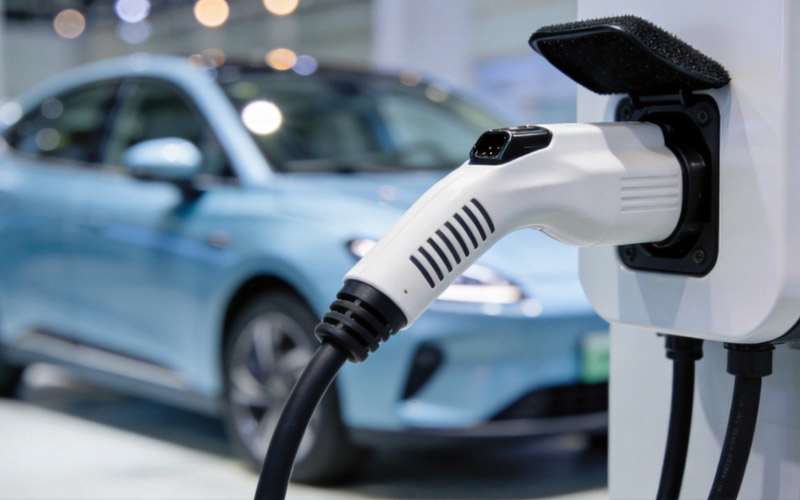
The liquid-cooled charging pile (also called the liquid-cooled supercharging pile) is built on high-power DC fast charging, adopting liquid cooling technology in place of traditional air-cooled heat dissipation. Its core purpose is to remove the heat from charging modules, charging gun cables and connectors through circulating coolant during high-current, high-power charging, thereby breaking through the air-cooled thermal bottleneck to deliver faster, safer and quieter charging.
Cooling Capability
Liquid cooling heat dissipation capability far exceeds air cooling, supporting larger current continuous output.Noise & Protection Level
The enclosed liquid cooling system isolates fan noise while raising the overall enclosure protection rating, making operation quieter and more reliable.Industry Scale
As of end-December 2025, China had 20.092 million EV charging facilities installed, up approximately 56.8% year on year — the world's largest EV charging network, supporting more than 40 million new energy vehicles.Micro Pump Suitability
In small charging piles and mobile charging equipment, micro liquid cooling pumps are widely used for their small size, low energy consumption and low noise; they can run on DC power and can be combined with renewable energy such as solar power for further energy saving and emission reduction.What Is a Liquid-Cooled Charging Pile?
The liquid-cooled charging pile (also called the liquid-cooled supercharging pile) is built on high-power DC fast charging, adopting liquid cooling technology in place of traditional air-cooled heat dissipation. Its core purpose is to remove the heat from charging modules, charging gun cables and connectors through circulating coolant during high-current, high-power charging, thereby breaking through the air-cooled thermal bottleneck to deliver faster, safer and quieter charging.
Industry Background and Trends
The network supports more than 40 million new energy vehicles.
Two Advantages Over Air Cooling
How Liquid Cooling Works in a Charging Pile
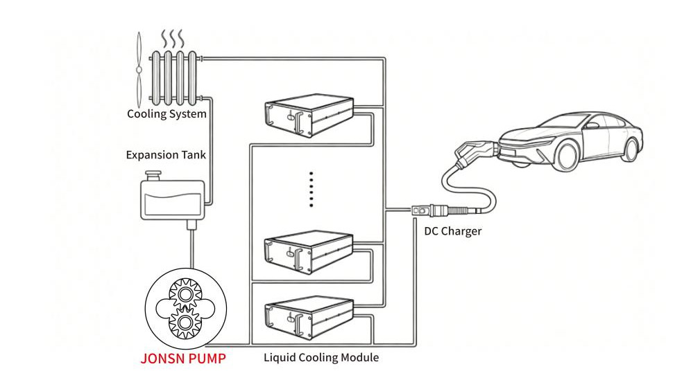
A liquid-cooled supercharging pile consists mainly of charging modules, charging guns, controllers, the liquid cooling system and the cabinet. The liquid cooling system drives coolant through a pump, circulating it to key heat-generating components such as charging modules, charging guns and controllers, so that efficient heat dissipation guarantees stable system operation.
Closed-Loop Working Principle of the Liquid-Cooled Charging Gun
This design allows a small cross-section cable to carry high current while meeting low temperature-rise requirements; the coolant is recycled, and the enclosed heat dissipation environment guarantees cleanliness while delivering superior heat dissipation performance and a longer service life compared with air cooling.
Role and Selection of Micro Liquid Cooling Pumps
The micro liquid cooling pump is the core component of the liquid cooling system, carrying out the key functions of medium flow delivery and pressure control, transferring coolant from inside the charging pile to the radiator. In high-power liquid-cooled supercharging piles, the pump transports media such as ethylene glycol aqueous solution or silicone oil to cool heat-generating parts such as cables and gun heads; in small charging piles and mobile charging equipment, micro liquid cooling pumps are widely used for their small size, low energy consumption and low noise, and can run on DC power or be combined with renewable energy such as solar power for further energy saving and environmental protection.
Selection Must Evaluate the Following Factors Comprehensively
Comparison of Common Pump Types in Charging Pile Liquid Cooling Systems
| Pump Type | Category | Characteristics | Limitations in Charging Pile Liquid Cooling Systems |
|---|---|---|---|
| Centrifugal Pump | Centrifugal kinetic pump | The higher the head, the lower the flow | Flow and head are constrained and the range of application is narrow; maintenance is difficult; some miniature water pumps have short service life and need frequent replacement |
| Diaphragm Pump | Plunger positive displacement pump | Fluid delivery is pulsed | Temperature-rise control is unstable; limited by diaphragm service life |
| Gear Pump | Rotary positive displacement pump | Stable flow, suitable for medium and high pressure; a century of application history | Conventional gear pumps are mainly used to convey media with lubricating properties |
| Vane Pump | Rotary positive displacement pump | Performance close to that of gear pumps | Vanes rub against the pump cylinder, wear easily, and wear particles contaminate the medium |
Comparison of Micro Magnetic Gear Pump Technical Routes
Once the gear pump route is settled, different manufacturer solutions must be compared from the material and process perspective. Current technical competition in micro magnetic gear pumps concentrates in three directions: PEEK gear and shaft material modification and processing technology, PEEK sliding bearing material and processing technology, and structural design optimisation.
5.1 PEEK Gear and Shaft Material Modification and Processing Technology
5.2 PEEK Sliding Bearing Material and Processing Technology
5.3 Structural Design Optimisation
The rear pump body and gear cavity are machined as one piece by CNC, giving high assembly precision
Fewer sealing rings, reducing leakage points
All clearances are guaranteed entirely by machining precision, giving good consistency and requiring no manual grinding and fitting
Large-bore internal flow channel design reduces resistance for greater energy efficiency and lower noise
Flexible interface configuration adapts to different installation requirements
5.4 Supporting Motor Technical Advantages
Motor performance directly affects the overall life of the pump. JONSN supporting motors use a shielded brushless structure:
JONSN-MRV Liquid-Cooled Charging Pile Solution
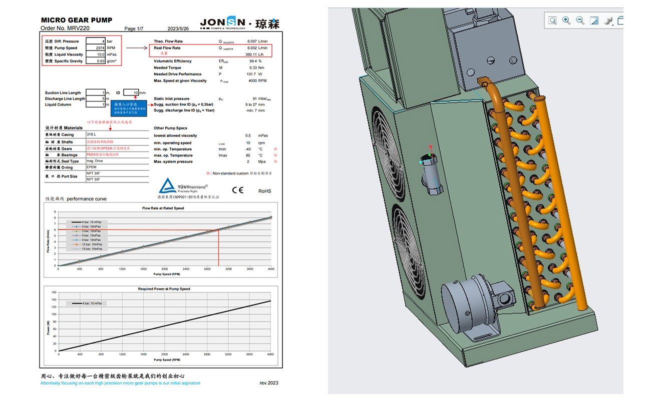
Taking a supercharging system with DC high-voltage charging power above 350 kW as an example, the typical operating parameters are as follows:
| Parameter | Specification |
|---|---|
| Cooling Medium | Silicone oil |
| Medium Viscosity | 10 mPa·s |
| Flow | 4–6 L/min |
| Operating Pressure | 4 bar |
| Power Supply | DC 24 V |
| Power | ≤ 150 W |
| Effective Operating Time | 25,000 hours |
Frequently Asked Questions
What advantages does a liquid-cooled charging pile have over an air-cooled charging pile?
The liquid-cooled charging pile uses circulating coolant in place of fan heat dissipation, with two main advantages. First, heat dissipation capability is stronger and supports larger charging current continuous output, giving faster charging speed. Second, the enclosed liquid cooling system isolates fan noise and raises the overall enclosure protection rating, making operation quieter and more reliable. Industry data shows the share of liquid-cooled piles in newly built public supercharging stations is forecast to exceed 80% in 2026.
Why does a liquid-cooled charging pile require a micro magnetic gear pump?
The liquid cooling system removes heat from charging modules, cables and connectors through coolant circulation, and the pump performs the core function of medium circulation and pressure control. Micro magnetic gear pumps are small in size, low in energy consumption and low in noise, and use a magnetic coupling for leak-free conveyance — particularly suited to the requirements of charging piles for compact space, long service life and cleanliness.
What advantages do micro magnetic gear pumps have over centrifugal, diaphragm and vane pumps?
Gear pumps are rotary positive displacement pumps with stable flow, suitability for medium and high pressure, and high reliability; centrifugal pumps have mutually constraining flow and head with a narrow range of application; diaphragm pumps deliver pulsed fluid with unstable temperature-rise control; vane pump vanes rub against the pump cylinder and wear easily, with wear particles contaminating the medium. On balance, gear pumps offer the greatest advantages in flow stability, pressure adaptability and reliability.
What are the characteristics of the PEEK gears and ceramic shafts of JONSN micro magnetic gear pumps?
JONSN uses imported high-strength wear-resistant PEEK gears from the UK with zirconia nano-ceramic shafts, formed by precision CNC hobbing plus high-temperature compression moulding heat treatment, giving high precision, dimensional stability and long life. The sliding bearings use a modified PEEK matrix with nano-ceramic composite, achieving a heavy-load service life of more than 20,000 hours. The integrated structure with static sealing rings gives small internal leakage, high precision and no manual grinding required.
Which model of liquid cooling pump should be selected for supercharging systems above 350 kW?
For supercharging operating conditions above 350 kW, with silicone oil as the medium (viscosity 10 mPa·s), flow 4–6 L/min, pressure 4 bar, DC 24 V and power ≤150 W, JONSN recommends model MRV220SZKL-TV (driven by a 150 W DC 24 V shielded brushless motor), with an effective operating time of up to 25,000 hours.